Device for collecting liquid samples from a vat

A technology for collecting liquids and samples, applied in sampling devices, measuring devices, sampling, etc., can solve problems such as inability to collect samples, excess liquid that cannot be completely returned to the vat, and difficulty in joining the vat, etc.

Inactive Publication Date: 2012-10-10
COMMISSARIAT À L ÉNERGIE ATOMIQUE & AUX ÉNERGIES ALTERNATIVES FR
View PDF5 Cites 1 Cited by
  • Summary
  • Abstract
  • Description
  • Claims
  • Application Information

AI Technical Summary

Problems solved by technology

[0003] A disadvantage of these devices is that excess liquid cannot be fully returned to the vat, and small droplets can remain on the conduit, which then crystallize: these crystals can be considered contamination and occur when the vat's original liquid has been replaced with another , these crystals can mix with later aspirated samples, limiting the quality of subsequent measurements
Another disadvantage of these devices is that it is difficult to engage a series of vats so that a sample cannot be selectively collected from any one of the series of vats

Method used


Image

  • Device for collecting liquid samples from a vat
  • Device for collecting liquid samples from a vat
  • Device for collecting liquid samples from a vat

Examples


Embodiment Construction

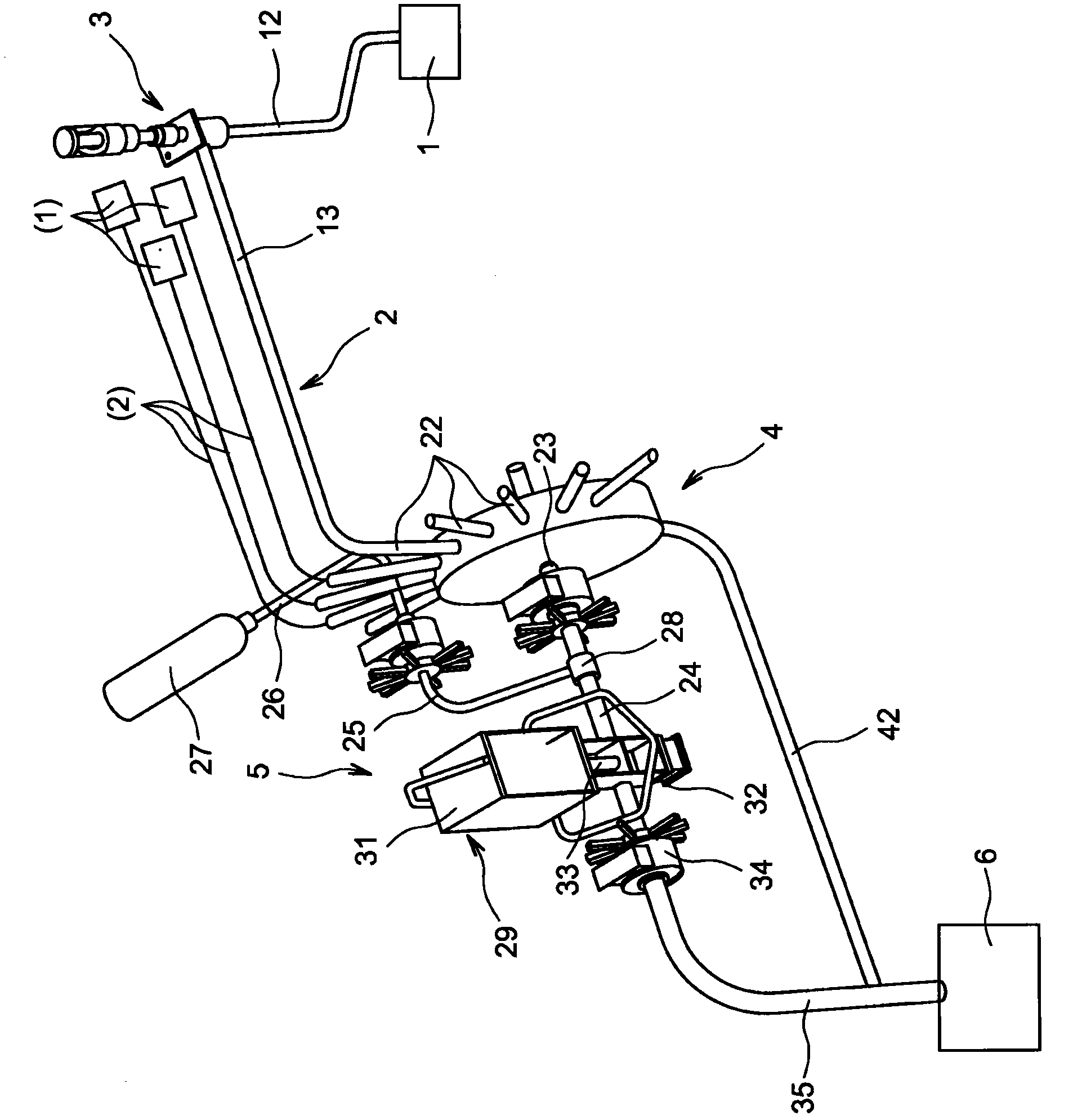
[0014] see first figure 1 . The liquid to be sampled is initially located in storage vat 1 . The conduits 2 for sampling leave the top of the vat 1, pass through the sampling facility 3, are each connected to a joint selector 4, then pass through the suction unit 5, and terminate at the outlet 6, which is used to collect excess Reservoir for suction liquid. The main elements of the device will now be described in turn. The conduit 2 first ascends from the vat 1 to the sampling facility 3 and then gradually descends towards the outlet 6, which is opposite the vat 1 and thus separated therefrom.

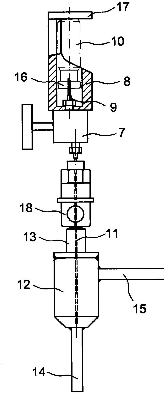
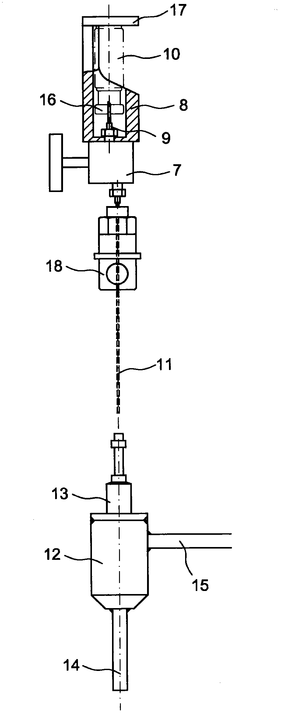
[0015] Figure 2 shows the sampling system 3 in detail. The sampling system 3 firstly comprises a movable part constituted by a manual valve 7 and a base via an injection needle 11, wherein the top of the manual valve 7 is occupied by a cylindrical sleeve 8 open at the top, which contains the upper Install the upper injection needle 9 of the liquid tank 10 and the pivoting part 17 ...


PUM


Abstract

The invention relates to a sampling system (3) to be arranged at the outlet of a vat (1) containing the liquid to be sampled, including a selector (4) that sets up switching among an array of similar vats (1), and especially a suction unit (5) that operates by releasing compressed air into a nozzle (28); the airflow direction is controlled by a valve (29), between a direction directed toward the outlet (6), causing the suction of the liquid from the vat (1), and an opposite direction when the valve (29) is closed, feeding the liquid back into the vat (1) and cleaning the pipe (2).

Description

technical field [0001] The present invention relates to a device for collecting a liquid sample from a vat, or even from multiple vats. Background technique [0002] Such devices are common in the nuclear industry and are used to analyze certain liquids laden with radioactive materials. The respective devices are usually placed in a shielded unit, and a remote operator is used to operate the respective devices. The liquid to be analyzed is initially contained in vats. The liquid undergoes suction through a conduit exiting in the top of the vat, which carries the liquid towards a sample holder on which a small container (commonly called a tank) has been mounted and which fills part of this tank . Once suction ceases, excess liquid drains to an outlet or flows through an inclined conduit back to the vat. [0003] A disadvantage of these devices is that excess liquid cannot be fully returned to the vat, and small droplets can remain on the conduit, which then crystallize: t...

Claims


Application Information

Patent Timeline
Patent Type & Authority Applications(China)
IPC IPC(8): G01N1/14
CPCG01N2001/1463G01N2001/1037G01N1/14G01N2033/0093
Inventor 克里斯多福·布內赫·拉葛瑞夫雅各·马蒙
Owner COMMISSARIAT À L ÉNERGIE ATOMIQUE & AUX ÉNERGIES ALTERNATIVES FR
Why Eureka
Try Eureka