Mold rotation type injection molding machine and rotary table rotation method

An injection molding machine and rotary technology, applied in the field of mold rotary injection molding machine and its turntable rotation, to achieve the effect of reducing costs and ensuring design freedom

Active Publication Date: 2014-08-13
JAPAN STEEL WORKS LTD
View PDF7 Cites 0 Cited by
  • Summary
  • Abstract
  • Description
  • Claims
  • Application Information

AI Technical Summary

Problems solved by technology

As a result, there is a problem that the thickness of the turntable must be equal to or greater than a certain value.

Method used


Image

  • Mold rotation type injection molding machine and rotary table rotation method
  • Mold rotation type injection molding machine and rotary table rotation method
  • Mold rotation type injection molding machine and rotary table rotation method

Examples


Embodiment Construction

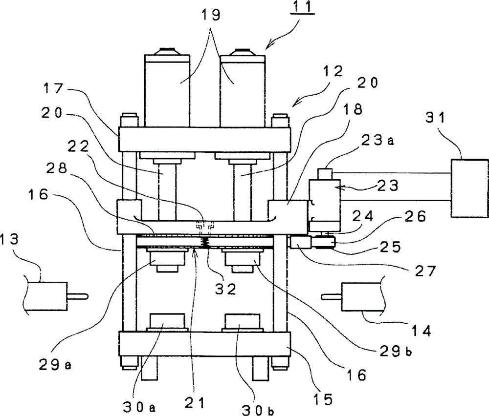
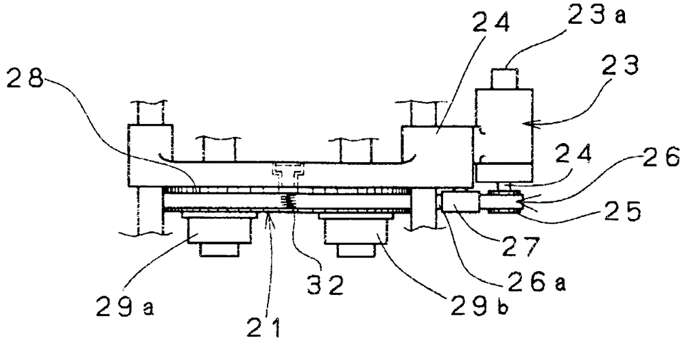
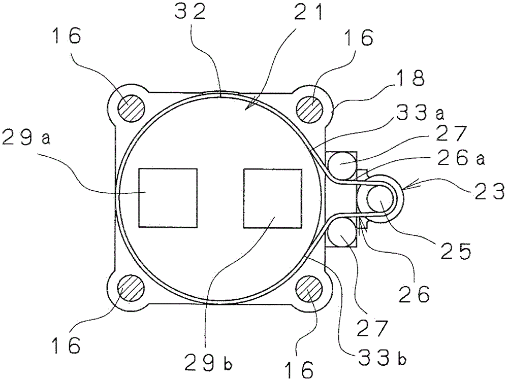
[0020] refer to Figure 1 ~ Figure 3 A mold rotary injection molding machine 11 according to an embodiment of the present invention will be described. A mold rotary injection molding machine 11 , which is a type of injection molding machine, basically includes a mold clamping device 12 , and a first injection device 13 and a second injection device 14 provided on both sides thereof. The clamping device 12 fixes four connecting rods 16 in the upright direction on the fixed disk 15 arranged below, and an upper disk 17 is fixed above the connecting rods 16 . In addition, the connecting rods 16 are inserted around the four corners of the movable platen 18 , and the movable platen 18 can move in the vertical direction between the fixed platen 15 and the upper plate 17 . In addition, a mold clamping cylinder 19 is provided on the upper plate 17 , and the piston 20 of the mold clamping cylinder 19 is fixed on the back surface of the movable plate 18 . In addition, an unillustrated ...


PUM


Abstract

PURPOSE: A mold rotating type injection mold machine and a method for rotating a rotation table thereof are provided to rotate a rotation table with a mold to a fixed board or movable board. CONSTITUTION: A mold rotating type injection mold machine(11) comprises a rotation table(21), a motor(23), and a belt(26). The rotation table has a belt hooking piece(28). The motor is installed near the side of the rotation table. The belt transfers driving force from the motor to the rotation table. A joint portion(32) of the belt touches the belt hooking piece of the rotation table to rotate the rotation table.

Description

technical field [0001] The present invention relates to a mold rotary injection molding machine and a method for rotating a turntable of the mold rotary injection molding machine. turntable. Background technique [0002] As a mold rotary injection molding machine provided with a turntable on which a mold is mounted so as to be rotatable relative to a fixed platen or a movable platen, there are a system using an electric motor as a driving source and a system using a hydraulic cylinder as a driving source. In recent years, The method of using electric motors as the driving source has become the mainstream. Among the methods using the motor as the driving source, the following methods are known: a method of transmitting the driving force of the motor to the central axis to rotate the turntable; method; and a method in which a timing belt is wound between the outer peripheral side of the turntable and the drive gear of the motor, and the driving force of the motor is transmit...

Claims


Application Information

Patent Timeline
Patent Type & Authority Patents(China)
IPC IPC(8): B29C45/06
CPCB29C45/0433B29C45/06B29C2045/1792
Inventor 谷雄介
Owner JAPAN STEEL WORKS LTD
Why Eureka
Try Eureka