Centrifugal fan and centrifugal blower

A centrifugal fan and fan technology, applied in the direction of mechanical equipment, machine/engine, liquid fuel engine, etc., can solve the problems that centrifugal fan cannot be avoided, cannot be designed independently, and the degree of freedom of blade design is reduced

Active Publication Date: 2021-07-23
DENSO CORP
View PDF7 Cites 0 Cited by
  • Summary
  • Abstract
  • Description
  • Claims
  • Application Information

AI Technical Summary

Problems solved by technology

[0010] In addition, as in the centrifugal fan of Patent Document 1, when the blades of the first fan and the blades of the second fan are directly connected without a separation plate, the blades of each fan cannot be arbitrarily designed.
That is, when the blades of the first fan and the blades of the second fan are directly conne...

Method used


Image

  • Centrifugal fan and centrifugal blower
  • Centrifugal fan and centrifugal blower
  • Centrifugal fan and centrifugal blower

Examples


Embodiment Construction

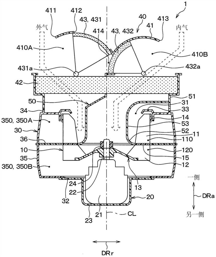
[0045] Below, based on Figure 1 to Figure 5 One embodiment of the present invention will be described. In the present embodiment, an example in which the centrifugal blower 1 of the present invention is applied to a vehicle air conditioner of a double-layer air conditioner capable of distinguishing the air outside the vehicle (hereinafter, It is called external air.) and the air in the vehicle interior (hereinafter referred to as internal air.) is blown into the vehicle interior.

[0046] Centrifugal blower 1 is arranged on the inner side of the instrument panel in the front part of the vehicle interior. like figure 1 As shown, the centrifugal blower 1 is configured to include a centrifugal fan 10 , a motor 20 , a fan case 30 , an inside and outside air switching unit 40 , and a separation cylinder 50 .

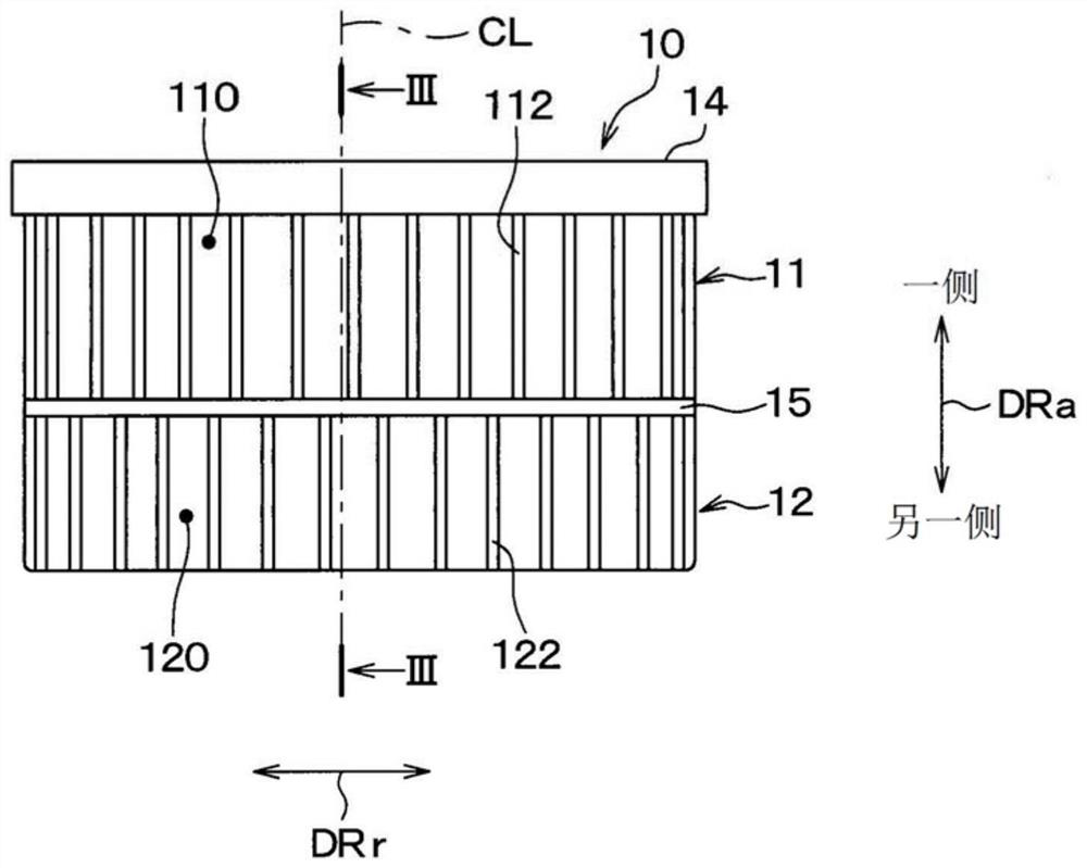
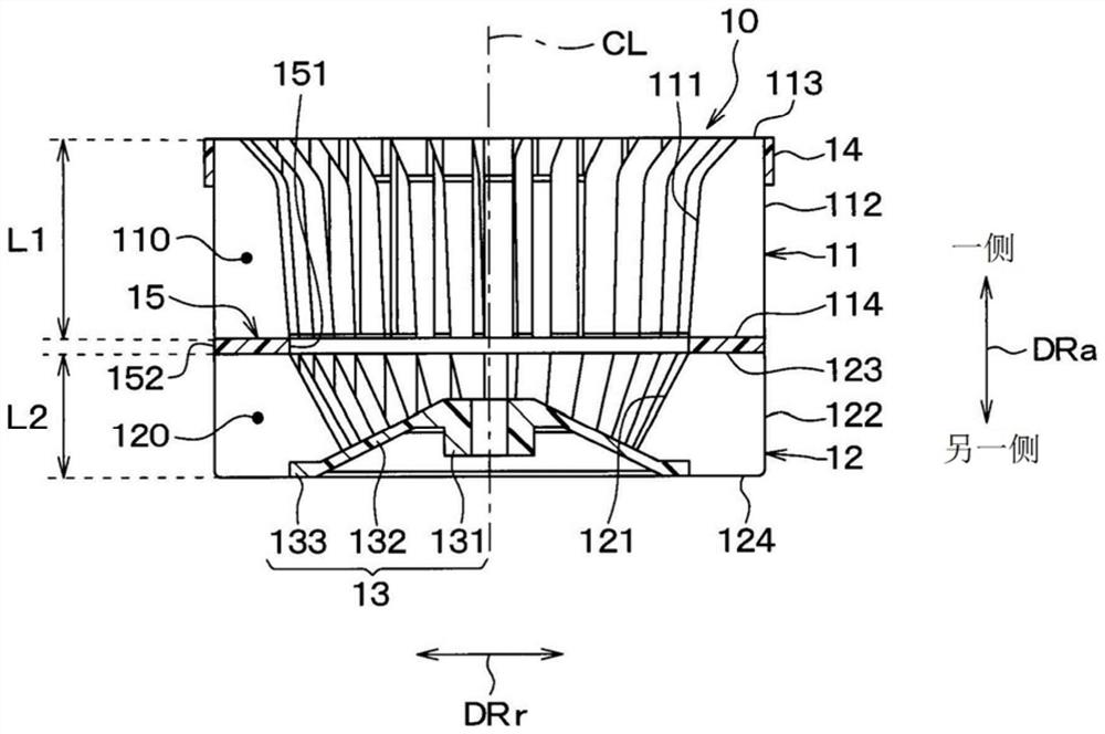
[0047] The centrifugal fan 10 is a fan that blows air taken in from the side of the fan axis CL in the axial direction DRa toward the outside in the radial direction DRr....


PUM


Abstract

A centrifugal fan (10) is equipped with a plurality of first blades (11), a plurality of second blades (12), a side plate (14), a main plate (13), and a separation plate (15). The plurality of first blades and plurality of second blades are not in direct contact, but are connected via the separation plate. For the front edge portion and rear edge portion of the plurality of the first blades, the diameter on the other side in the axial direction is less than or equal to the diameter on the one side in the axial direction. For the front edge portion and rear edge portion of the plurality of the second blades, the diameter on the other side in the axial direction is less than or equal to the diameter on the one side in the axial direction. For the separation plate, the separation plate inner diameter is greater than or equal to the main plate outer diameter, greater than or equal to a second front edge diameter, and less than or equal to a first front edge diameter, and the separation plate outer diameter is less than or equal to the side plate inner diameter, greater than or equal to a second rear edge diameter, and less than or equal to a first rear edge diameter.

Description

[0001] Cross-references to related applications [0002] This application is based on Japanese Patent Application No. 2018-234595 filed on December 14, 2018, and the contents described therein are incorporated herein by reference. technical field [0003] The present invention relates to a centrifugal fan and a centrifugal blower provided with the centrifugal fan. Background technique [0004] In the past, as a centrifugal blower applied to a vehicle air conditioner of a double-flow type of inside and outside air, a centrifugal blower capable of simultaneously sucking in air outside the vehicle and air inside the vehicle from one side of the axial direction of the fan axis is known (for example, refer to Patent Document 1). [0005] In this patent document 1, a centrifugal fan provided with a separation plate that separates the air blown from the centrifugal fan into an air flow on one side in the axial direction and a flow on the other side is disclosed as a centrifugal fa...

Claims


Application Information

Patent Timeline
IPC IPC(8): F04D29/44F04D29/62F04D29/24
CPCF05D2240/303F04D29/281F04D17/16F04D25/08F04D29/441F04D29/023F04D29/4213B60H1/00471B60H2001/00085F04D29/4226F04D29/444
Inventor 小坂翔小田修三
Owner DENSO CORP
Why Eureka
Try Eureka