Locking device and demountable tanker carrier

A technology of locking device and limiting device, which is applied in the direction of tilt-bearing moving vehicles, etc., can solve the problems of damage to the back tanker, low use efficiency, waste of manpower, etc., and achieve overload protection, improve work efficiency, and reduce manpower waste. Effect

Inactive Publication Date: 2012-10-17
SANY HEAVY IND CO LTD (CN)
View PDF5 Cites 11 Cited by
  • Summary
  • Abstract
  • Description
  • Claims
  • Application Information

AI Technical Summary

Problems solved by technology

[0003] However, during work, the auxiliary oil cylinder will not stay at the position lifted to a certain angle due to the effect of gravity, but will naturally fall back due to the effect of gravity, leaving the position of the interface of the lifting arm, resulting in the failure of the lifting arm in the process of recovery. Quasi-auxiliary oil cylinder, at this time, it is often necessary for one person to hold the auxiliary oil cylinder and align it with the lifting arm, and another person can operate the valve block to recover to the initial state, resulting in a waste of manpower and a reduction in the working efficiency of the tanker; at the same time, the auxiliary oil cylinder is due to The piston rod is stretched out, causing the center of gravity to lean upwards. After falling back naturally, the piston rod is easy to collide with the nearby oil cylinder seat, so that the piston rod is damaged, causing the oil cylinder to leak and be scrapped. The damage of the oil cylinder is easy to cause the lifting arm and the moving silo Failure during the lifting and recovery process, resulting in unpredictable safety accidents, and a series of problems such as damage to the tanker, high maintenance costs and low efficiency of the tanker
[0004] Therefore, how to ensure that the auxiliary cylinder stays in the position aligned with the interface of the lifting arm after lifting the lifting arm, improve the working efficiency of the tank truck, and avoid damage to the cylinder caused by the natural fall of the auxiliary cylinder is a problem for those skilled in the art. Urgent technical issues to be resolved

Method used


Image

  • Locking device and demountable tanker carrier
  • Locking device and demountable tanker carrier
  • Locking device and demountable tanker carrier

Examples


Embodiment Construction

[0041] In order to understand the above-mentioned purpose, features and advantages of the present invention more clearly, the present invention will be further described in detail below in conjunction with the accompanying drawings and specific embodiments.

[0042] In the following description, many specific details are set forth in order to fully understand the present invention. However, the present invention can also be implemented in other ways different from those described here. Therefore, the protection scope of the present invention is not limited by the specific details disclosed below. EXAMPLE LIMITATIONS.

[0043] The present invention will be further described below in conjunction with the accompanying drawings and embodiments. It should be noted that, in the case of no conflict, the embodiments of the present application and the features in the embodiments can be combined with each other.

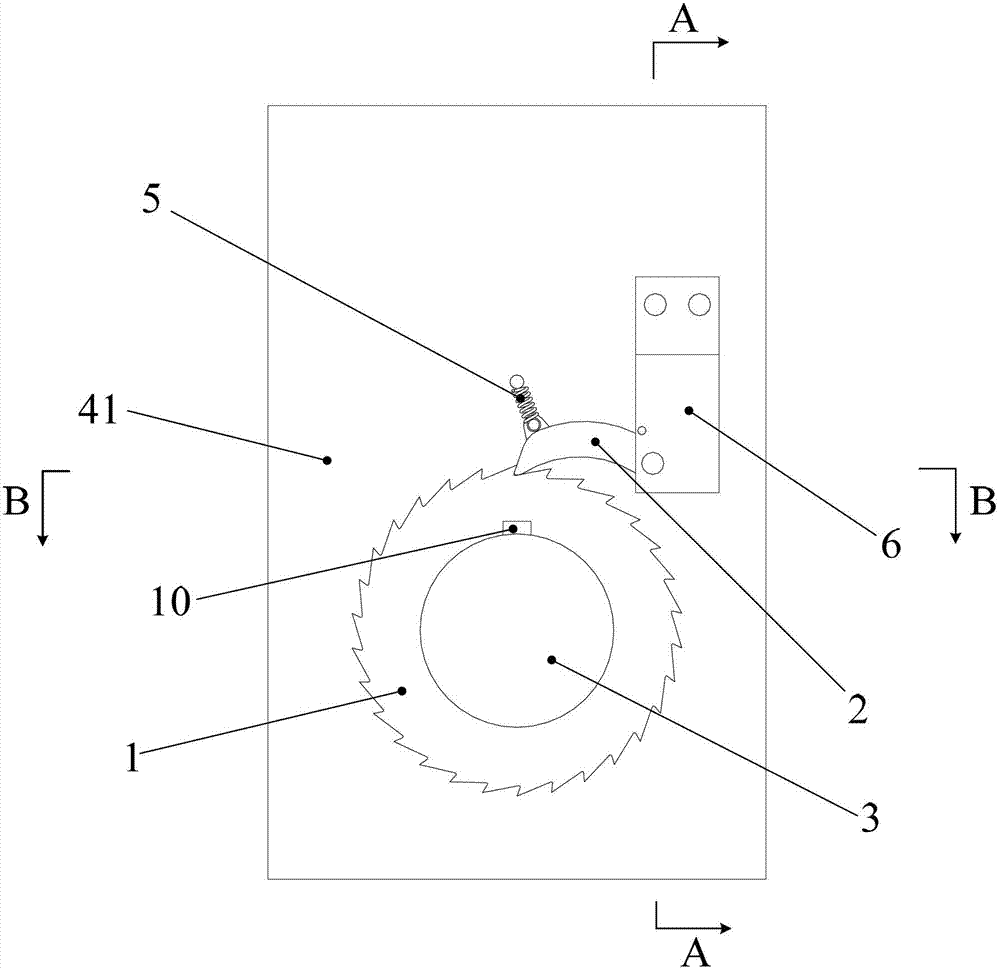
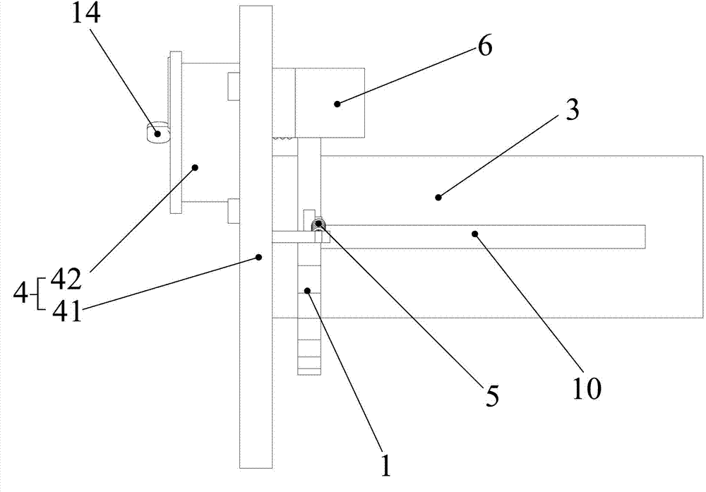
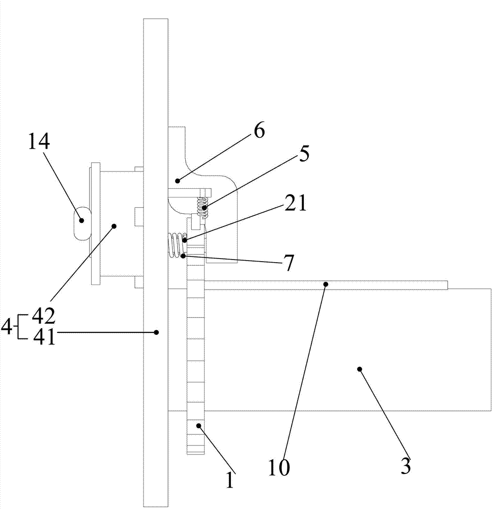
[0044] Such as Figure 1 to Figure 5 As shown, the locking device in th...


PUM


Abstract

The invention provides a locking device. The locking device comprises a first ratchet, a first pawl, a first rotating shaft and a fixed part, wherein the first rotating shaft is rotatably arranged on the fixed part; the first pawl is arranged on the first rotating shaft and can synchronously rotate along with the first rotating shaft; the first pawl is arranged on the fixed part; and the first pawl is matched with the first ratchet to lock the first rotating shaft. By utilizing the locking device, an auxiliary oil cylinder is guaranteed to stay at a position aligned to a joint of a hoisting arm after the hoisting of the hoisting arm is finished, so that the working efficiency of a demountable tanker carrier is improved, and the phenomenon that the oil cylinder is damaged because the oil cylinder naturally falls back is avoided. The invention also provides the demountable tanker carrier.

Description

technical field [0001] The invention relates to the field of mechanical structures, in particular to a locking device and a tank truck. Background technique [0002] During the working process of the tank truck, the lifting arm of the tank truck and the moving silo are continuously lifted and recovered. During the lifting process, the auxiliary cylinder is required to lift the lifting arm and the moving silo with a certain force. After lifting to a certain angle, the lifting arm and the moving silo are lifted up through the relay of the lifting cylinder; during the recovery process, the lifting cylinder is slowly recovered first, and then the auxiliary cylinder is aligned with the lifting cylinder. The interface of the lifting arm is recovered to the initial state by relay. [0003] However, during work, the auxiliary oil cylinder will not stay at the position lifted to a certain angle due to the effect of gravity, but it will naturally fall back due to the effect of gravit...

Claims


Application Information

Patent Timeline
Patent Type & Authority Applications(China)
IPC IPC(8): B60P1/20
Inventor 蒋志辉田伟卢丽
Owner SANY HEAVY IND CO LTD (CN)
Why Eureka
Try Eureka