Rotor blade de-icing system

一种旋翼、叶片的技术,应用在除冰系统领域,能够解决增加飞行器整体重量等问题,达到消除结冰的效果

Inactive Publication Date: 2012-10-17
BELL HELICOPTER TEXTRON INC
View PDF4 Cites 8 Cited by
  • Summary
  • Abstract
  • Description
  • Claims
  • Application Information

AI Technical Summary

Problems solved by technology

However, slip rings add to the overall weight of the aircraft and lead to additional maintenance costs
[0007] While the deicing systems described above have made great strides, there are still considerable shortcomings

Method used


Image

  • Rotor blade de-icing system
  • Rotor blade de-icing system
  • Rotor blade de-icing system

Examples


Embodiment Construction

[0036] Exemplary embodiments of the present systems and methods are described below. It should be appreciated that in the development of any such actual implementation, numerous implementation-specific decisions must be made to achieve the developer's specific goals, such as compliance with system-related and business-related constraints, which will vary between various implementations. varies. In addition, it should be appreciated that such a development effort might be complex and time consuming, but would still be within the routine skills of one of ordinary skill in the art having the benefit of this disclosure.

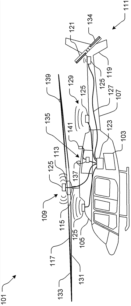
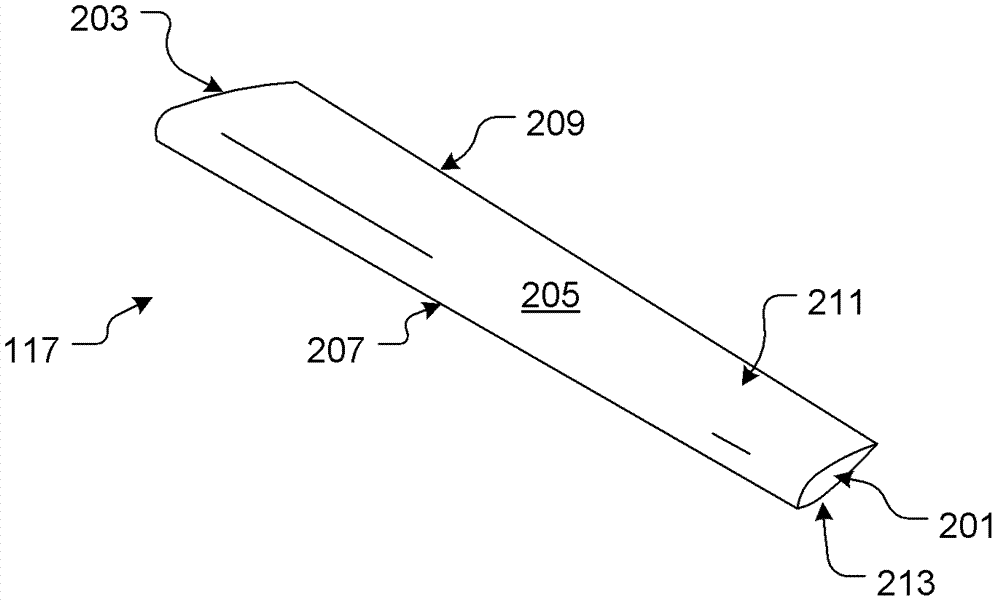
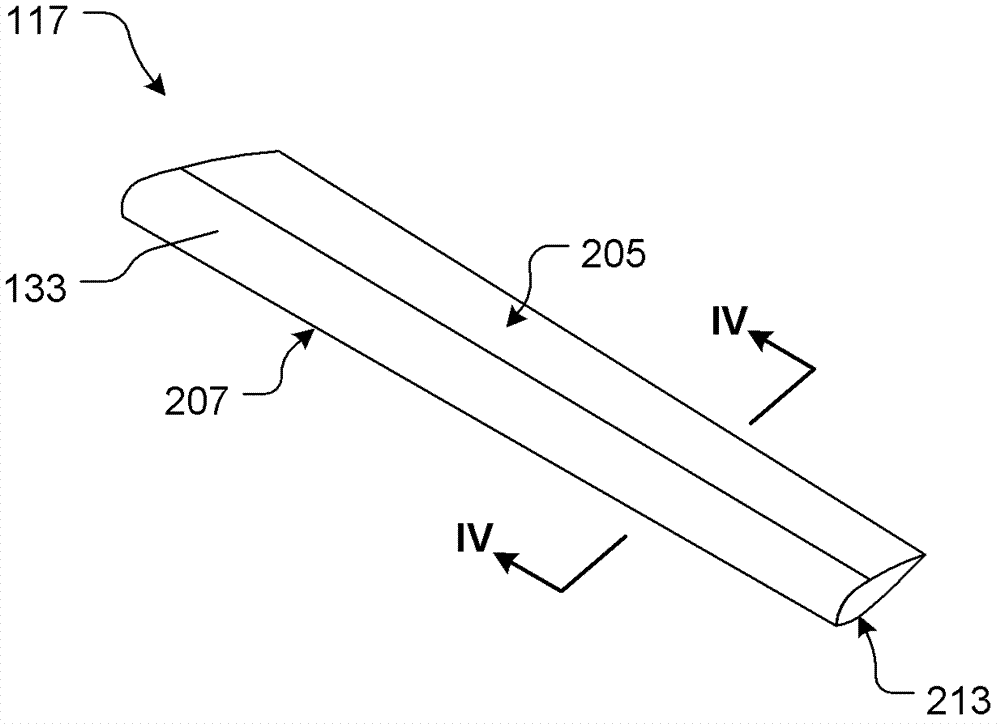
[0037] The deicing system of the present application eliminates icing without running wires through the rotor mast and / or using slip rings, overcoming common problems with conventional deicing systems. The system includes means for transferring thermal energy to heat absorbing material carried by the rotor blades. The absorbed heat energy then warms the rotor b...


PUM


Abstract

The invention discloses a rotor blade de-icing system. An aircraft (101) includes a heat absorbent material (131) carried by an airfoil (117) susceptible to ice buildup and a transmitter (125) spaced apart from the heat absorbent material (131). A method includes the process of transmitting the heat energy from the transmitter (125) to the heat absorbent material (131) that in turn warms the airfoil (117) to break apart ice buildup. The de-icing system of the invention does not need to make an electric wire penetrate a rotor mast and / or use a collecting ring to eliminate the icing, thereby overcoming the common problems existing in the conventional de-icing system.

Description

[0001] Cross References to Related Applications [0002] This application is the official U.S. Application No. 61 / 473,189, filed April 8, 2011, entitled "Helicopter Rotor Blade De-Icing Using Microwave Energy," which is hereby incorporated by reference for all purposes as if incorporated herein by reference. The full text is presented in this paper as well. technical field [0003] The present application relates generally to a deicing system, and more particularly to a deicing system for a rotorcraft. Background technique [0004] Aircraft operating in icy weather conditions must employ one or more deicing systems for breaking up ice that has formed on the wings, rotors, and / or other airfoil structures used to generate lift. Conventional rotorcraft, such as helicopters, generate lift through rotor blades that are susceptible to icing. Icing causes the aircraft to lose lift, which in turn may cause the aircraft to crash. [0005] Existing rotor blade deicing systems usual...

Claims


Application Information

Patent Timeline
Patent Type & Authority Applications(China)
IPC IPC(8): B64D15/12
CPCH05B6/80B64D15/12H02J17/00
Inventor J·M·麦科洛R·奥伯特
Owner BELL HELICOPTER TEXTRON INC
Why Eureka
Try Eureka