Blowby gas returning apparatus for engine with supercharger
A blow-by gas and return device technology, which is applied in the direction of machines/engines, engine components, mechanical equipment, etc., can solve the problems of not being able to return to the engine, and achieve the effect of easy piping operations
- Summary
- Abstract
- Description
- Claims
- Application Information
AI Technical Summary
Problems solved by technology
Method used
Image
Examples
no. 1 Embodiment approach
[0034] Hereinafter, a first embodiment of the blow-by gas returning device for an engine with a supercharger according to the present invention will be described in detail with reference to the drawings.
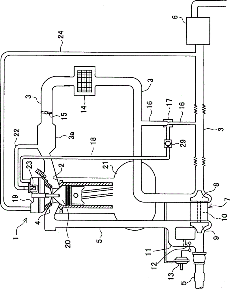
[0035] figure 1 An engine system including a blow-by gas return device of an engine with a supercharger in this embodiment is shown using a schematic structural diagram in . The engine system has a reciprocating engine 1 . An intake passage 3 is connected to an intake port 2 of the engine 1 , and an exhaust passage 5 is connected to an exhaust port 4 . An air filter 6 is provided at the inlet of the intake passage 3 . A supercharger 7 for boosting the intake air in the intake passage 3 is provided between the intake passage 3 and the exhaust passage 5 at a position downstream of the air cleaner 6 in the intake passage 3 .
[0036] The supercharger 7 includes a compressor 8 arranged in the intake passage 3 , a turbine 9 arranged in the exhaust passage 5 , and a rotary shaf...
no. 2 Embodiment approach
[0065] Next, a second embodiment of the blow-by gas returning device for an engine with a supercharger according to the present invention will be described in detail with reference to the drawings.
[0066] In addition, in each of the embodiments described below, the same reference numerals are assigned to the same components as those in the above-mentioned first embodiment, and description thereof will be omitted, and the description will focus on differences.
[0067] Figure 6 An engine system including a blow-by gas return device of an engine with a supercharger in this embodiment is shown using a schematic structural diagram in . In this embodiment, a vacuum control valve (VSV) 31 is provided in the vicinity of the injector 17 of the first blow-by gas return passage 18 instead of the check valve 29 of the first embodiment. The VSV 31 is controlled by an electronic control unit (ECU) 32 according to the operating state of the engine 1 . The configuration of this embodime...
no. 3 Embodiment approach
[0076] Next, a third embodiment of the blow-by gas return device for an engine with a supercharger according to the present invention will be described in detail with reference to the drawings.
[0077] Figure 8 An engine system including a blow-by gas return device of an engine with a supercharger in this embodiment is shown using a schematic structural diagram in . In this embodiment, the check valve 29 provided in the first blow-by gas return passage 18 in the first embodiment described above is omitted. Instead, the structure of the partitions 28A, 28B of the cylinder head cover 19 differs from the structure of the first embodiment.
[0078] Figure 9 The two partitions 28A, 28B in the cylinder head cover 19 are schematically shown in FIG. Such as Figure 9As shown, two different partitions 28A, 28B separated from each other are provided in the cylinder head cover 19 . Each of the partitions 28A, 28B includes an inlet 28a and a plurality of blades 28b arranged in a l...
PUM
 Abstract
Description
Claims
Application Information
 - R&D
- Intellectual Property
- Life Sciences
- Materials
- Tech Scout
- Unparalleled Data Quality
- Higher Quality Content
- 60% Fewer Hallucinations
Browse by: Latest US Patents, China's latest patents, Technical Efficacy Thesaurus, Application Domain, Technology Topic, Popular Technical Reports.
© 2025 PatSnap. All rights reserved.Legal|Privacy policy|Modern Slavery Act Transparency Statement|Sitemap|About US| Contact US: help@patsnap.com


