High-strength impeller

A high-strength, impeller technology, applied to the components of pumping devices for elastic fluids, non-variable pumps, machines/engines, etc., can solve problems such as blade breakage and shorten the service life of impellers, and achieve not easy to break, The effect of increasing the service life and reducing the transmission pressure

Inactive Publication Date: 2012-10-17
SUZHOU TAIHU FAN MFG
View PDF0 Cites 1 Cited by
  • Summary
  • Abstract
  • Description
  • Claims
  • Application Information

AI Technical Summary

Problems solved by technology

Since the fan blades are generally welded to the front cover and the rear cover, the fulcrum of the force that drives the fan blades to rotate during the rotation of the impeller is the welding between the fan blades, the front cover and the rear cover. Point, in the long-term use process, the blade will break due to excessive transmission pressure, shortening the service life of the impeller

Method used


Image

  • High-strength impeller

Examples


Embodiment Construction

[0012] The present invention is described below in conjunction with accompanying drawing.

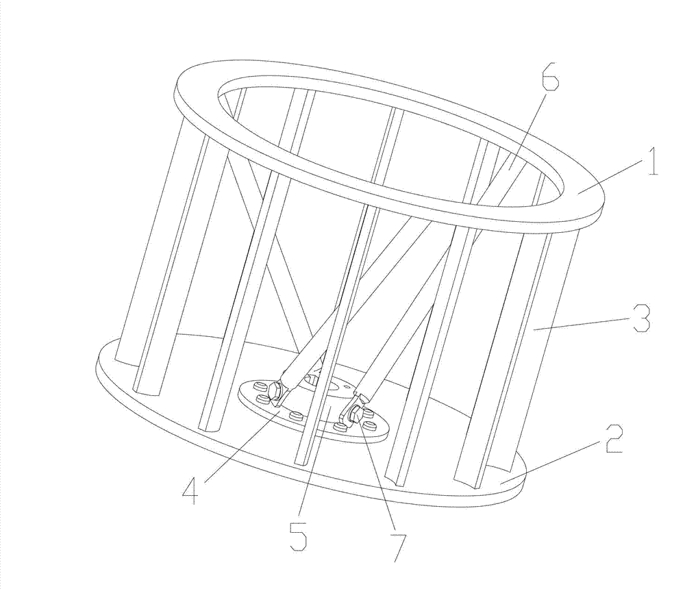
[0013] as attached figure 1 The shown high-strength impeller of the present invention includes a front cover 1, a rear cover 2 and blades 3, and there are multiple blades 3 in an annular array between the front cover 1 and the rear cover 2, so The inner surface of the rear cover 2 is provided with a connection plate 4; the center of the connection plate 4 is provided with a pivot 5, and at least two reinforcing ribs 6 are connected between the front cover 1 and the rear cover 2; One end of the reinforcing rib 6 is welded to the front cover 1 , and the other end is fixed on the side surface of the pivot 7 through the pin 7 .

[0014] During the rotation process of a high-strength impeller according to the present invention, the blade 3 and the pivot 5 are driven by the back cover 2 to rotate, so that the blade 3 and the rib 6 fixed on the side surface of the pivot 7 drive the front Whe...


PUM


Abstract

The invention discloses a high-strength impeller. The high-strength impeller comprises a front cover plate, a back cover plate and blades, wherein a plurality of blades in an annular array are arranged between the front cover plate and the back cover plate; a connecting plate is arranged on the inner surface of the back cover plate; a pivot is arranged at the center of the connecting plate; and at least two reinforcing ribs are connected between the front cover plate and the back cover plate. In the process of rotation of the high-strength impeller, the back cover plate drives the blades and the reinforcing ribs to rotate, the blades and the reinforcing ribs drive the front cover plate to rotate, and the reinforcing ribs share the transmission pressure of the blades in the process of rotation, so that the transmission pressure of the blades in the process of rotation is greatly reduced, the blades can not be easily ruptured, and the service life of the impeller is further prolonged.

Description

technical field [0001] The invention relates to an impeller, in particular to a high-strength impeller. Background technique [0002] As a key component of the fan, the impeller's structural configuration directly affects the overall performance of the fan. When the impeller is rotating, the rear cover plate drives the blades to rotate, and the blades drive the front cover plate to rotate, thereby realizing the rotation of the entire impeller. Since the fan blades are generally welded to the front cover and the rear cover, the fulcrum of the force that drives the fan blades to rotate during the rotation of the impeller is the welding between the fan blades, the front cover and the rear cover. Point, in the long-term use process, the blade will break due to excessive transmission pressure, shortening the service life of the impeller. Contents of the invention [0003] In view of the above-mentioned technical problems, the object of the present invention is to propose a hi...

Claims


Application Information

Patent Timeline
Patent Type & Authority Applications(China)
IPC IPC(8): F04D29/28
Inventor 汤永明
Owner SUZHOU TAIHU FAN MFG
Why Eureka
Try Eureka