Hyperbolic concave refractive and reflective panorama camera and making method and application thereof

A technology of catadioptric panoramic and concave mirrors, which is applied in the direction of cameras, camera bodies, image data processing, etc., can solve the problems of large mirror distortion, difficult center position processing, and large amount of real-time processing calculations, etc., to achieve applicable wide range of effects

Inactive Publication Date: 2015-02-04
NAT UNIV OF DEFENSE TECH
View PDF7 Cites 0 Cited by
  • Summary
  • Abstract
  • Description
  • Claims
  • Application Information

AI Technical Summary

Problems solved by technology

However, the images directly collected by the existing catadioptric panoramic imaging system are greatly distorted and have low edge resolution. If the images are stitched together, inverse perspective transformation is required, and the real-time processing requires a large amount of calculation, which requires high requirements for computer hardware. Require
Gaspar J. et al. proposed the emergence of a horizontal equal-scale mirror (see Constant resolution omnidirectional cameras for literature, included in Proceedings of Third Workshop on Omnidirectional Vision, Copenhagen, Denmark (held with ECCV02), 2002:27-34), using the mirror surface The imaging distortion of the panoramic imaging system is small in the horizontal scene, but the distortion of the mirror in the vertical scene is very large, and the profile curve that constitutes the mirror surface has only a numerical solution, and its center position is difficult to process, resulting in almost no imaging in the center of the panorama

Method used


Image

  • Hyperbolic concave refractive and reflective panorama camera and making method and application thereof
  • Hyperbolic concave refractive and reflective panorama camera and making method and application thereof
  • Hyperbolic concave refractive and reflective panorama camera and making method and application thereof

Examples


Embodiment

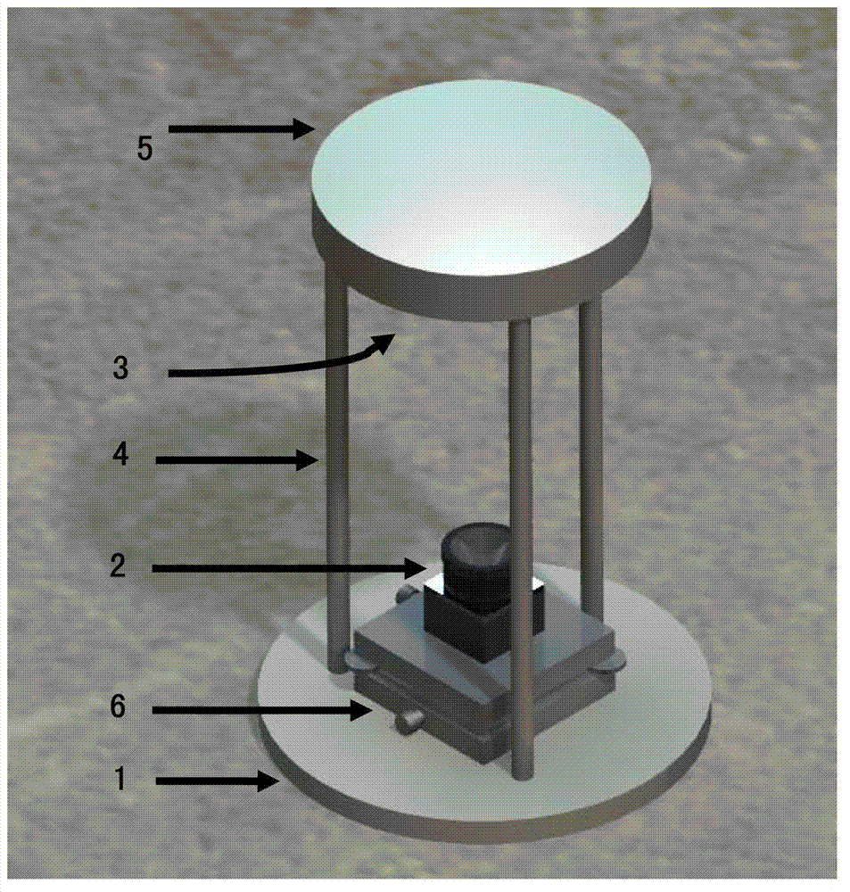
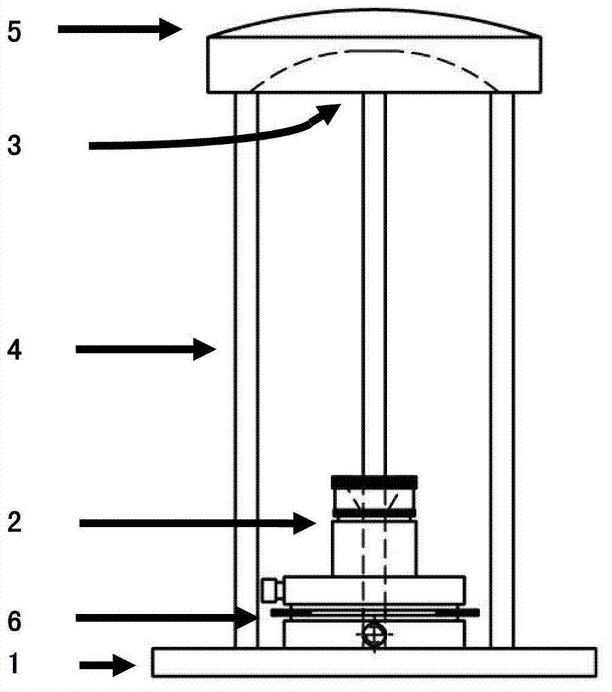
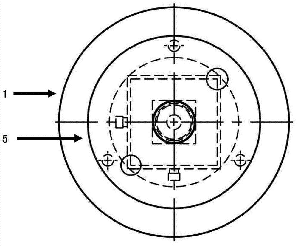
[0041] a kind of like Figure 1 ~ Figure 4 Shown is a hyperbolic concave catadioptric panoramic camera of the present invention that can be installed on a vehicle platform to collect road surface image information. The panoramic camera includes a base 1 that can be installed on a vehicle platform and an ordinary perspective camera 2 installed on the base 1. The lens front of common see-through camera 2 is provided with the hyperbolic concave reflector 3 that can be used for reflecting road surface image, and top cover 5 is installed on the top of hyperbolic concave reflector 3, and the optical axis of hyperbolic concave reflector 3 is the same as that of common see-through camera 2. The optical axes coincide, and the hyperbolic concave reflector 3 is connected to the base 1 through a liftable bracket 4 .

[0042] In the hyperbolic concave catadioptric panoramic camera of the present embodiment, the liftable support 4 is a tripod support frame, and the three support legs of the...


PUM


Abstract

The invention discloses a hyperbolic concave refractive and reflective panorama camera and a making method and application thereof. The panorama camera comprises a base and a common perspective camera which can be arranged on a vehicular platform; a hyperbolic concave reflector for reflecting pavement images is arranged in front of a lens of the common perspective camera; the optical axis of the hyperbolic concave reflector is superposed with the common perspective camera; and the hyperbolic concave reflector is connected to the base through a lifting support. The making method comprises the following steps of: establishing a hyperbolic concave refractive and reflective panorama camera model, determining the distance between the hyperbolic concave reflector and the perspective center of the common perspective camera, determining lens focus of the common perspective camera and charge coupled device (CCD) size, erecting the common perspective camera support, and calibrating the camera. The panorama camera has the characteristics of simple structure, easiness in assembly and the like, and can be used for acquiring pavement image information in the highway survey process; and the acquired images have low distortion in horizontal scenes and vertical scenes.

Description

technical field [0001] The invention relates to the fields of photogrammetry, image processing and optical design, and further relates to a camera for panoramic imaging using a hyperbolic concave mirror and a common perspective camera and its manufacture and application. Background technique [0002] The construction of expressways in our country started late, with limited construction experience and level. There are more or less diseases on the expressways that have been opened to traffic or are under construction. It directly affects the quality and normal operation of expressways. Some serious diseases, such as road surface Cracking, sinking, voiding, wrong platform, roadbed deformation, etc., will also directly threaten the driving safety of vehicles running on the expressway. Facing such a huge road network, the supporting road quality monitoring and maintenance equipment also needs to be researched and developed urgently. [0003] The traditional road surveying method...

Claims


Application Information

Patent Timeline
Patent Type & Authority Patents(China)
IPC IPC(8): G03B37/00G03B17/56G03B17/17G06T7/00
Inventor 冯莹马相路曹毓赵立双李武男
Owner NAT UNIV OF DEFENSE TECH
Why Eureka
Try Eureka