Direct type backlight module and liquid crystal displayer

A liquid crystal display and backlight module technology, applied in the directions of instruments, optics, light sources, etc., can solve the problems of dark spots on diffuser plates, dark spots on optical modules, etc., and achieve the effect of improving shadows

Active Publication Date: 2014-08-27
TCL CHINA STAR OPTOELECTRONICS TECH CO LTD
View PDF6 Cites 0 Cited by
  • Summary
  • Abstract
  • Description
  • Claims
  • Application Information

AI Technical Summary

Problems solved by technology

[0008] The purpose of the present invention is to overcome the problem of dark spots on the optical die caused by the supporting structure of the existing backlight module, and provide a new type of backlight module. A technical problem to be solved is to make it possible to solve the problem because the supporting structure is blocked. The path of light, thus creating shadows on the diffuser plate, which seriously affects the quality of the picture
[0009] The secondary purpose of the present invention is to overcome the support structure of the backlight module in the existing liquid crystal display and produce dark spots on the diffusion plate, and provide a new type of backlight module. A technical problem to be solved is to make it possible to solve Because the support structure blocks the path of light, shadows are generated on the diffuser plate, which seriously affects the quality of the picture

Method used


Image

  • Direct type backlight module and liquid crystal displayer
  • Direct type backlight module and liquid crystal displayer
  • Direct type backlight module and liquid crystal displayer

Examples


Embodiment Construction

[0029] Further details will be given below in conjunction with the preferred embodiments shown in the accompanying drawings.

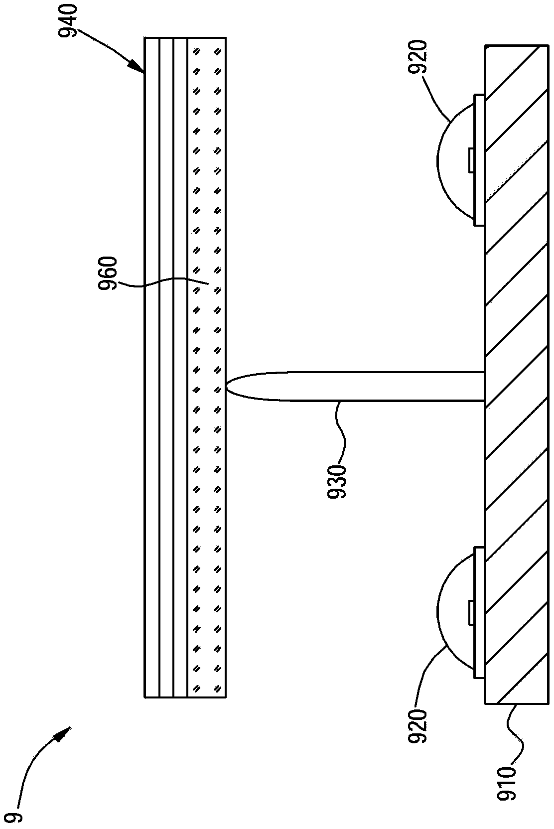
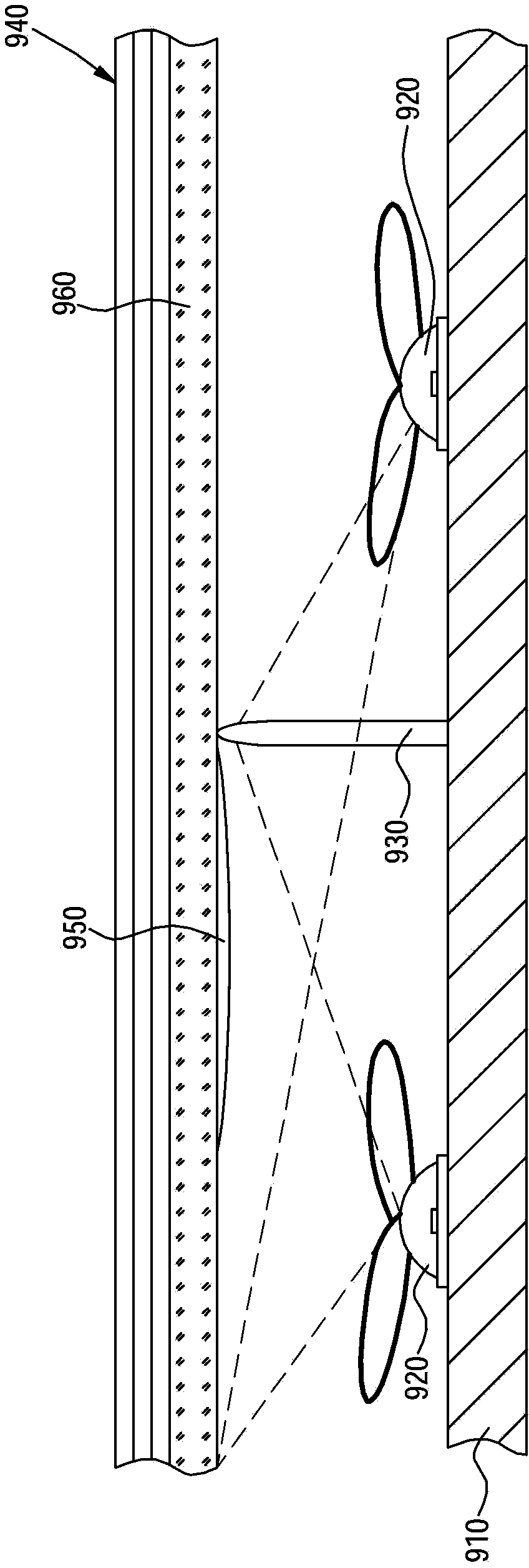
[0030] Figure 4 It is a partial sectional view of the direct type backlight module according to the first embodiment of the present invention. Such as Figure 4 As shown, the direct type backlight module 1 includes an optical module 140, a diffusion plate 160, a bottom plate 110, a plurality of light emitting diodes 120 and a plurality of support structures 130, for the convenience of description, Figure 4 Only two LEDs 120 and one support structure 130 are shown. The supporting structure 130 includes a top 131 and a bottom 132 .

[0031] The top of the diffuser plate 160 carries the optical film 140; the bottom plate 110 is arranged below the diffuser plate 160; Between the plate 160 and the bottom plate 110 , the bottom 132 of the support structure 130 is fixed on the bottom plate 110 . The top 131 of the supporting structure 130 is a helical ...


PUM


Abstract

A direct-lit backlight module (1) and a liquid crystal display device comprising same. The direct-lit backlight module comprises: an optical film (140), a diffusion panel (160) supporting the optical film (140), a base panel (110) arranged below the diffusion panel (160), a plurality of light-emitting diodes (120) arranged between the diffusion panel (160) and the base panel (110), and a plurality of support structures (130) arranged between the diffusion panel (160) and the base panel (110) and fixed onto the base panel (110). Each of the support structures (130) comprises a top part (131) having a translucent area (133), where the translucent area (133) allows the passage of a light emitted by the light-emitting diodes (120), and a bottom part fixed onto the base panel. The direct-lit backlight module (1) and the liquid crystal display device (2) improve on the problem of a shadow casted on the diffusion panel (160).

Description

technical field [0001] The present invention relates to a direct-type backlight module and a liquid crystal display using the direct-type backlight module, in particular to a support structure capable of reducing shadows. Background technique [0002] In recent years, direct-type backlight modules using light-emitting diodes (LEDs) have attracted widespread attention for their advantages such as easy local dimming, high uniformity, and no mercury pollution. There are two common implementation forms of direct-type LED backlight modules, one is to directly use surface-mounted LEDs (usually a large number of LEDs are required), and the second is to use surface-mounted LEDs with a secondary lens (The number of LEDs can be reduced). But no matter which implementation form is adopted, the diffuser plate needs to have a supporting structure to prevent its deformation due to thermal expansion and contraction and vibration during transportation, causing taste problems or damage to t...

Claims


Application Information

Patent Timeline
Patent Type & Authority Patents(China)
IPC IPC(8): F21S8/00F21V21/00G02F1/13357F21Y101/02
CPCG02F1/133606G02F1/133611F21V21/00G02F1/133603G02F1/133608
Inventor 胡哲彰张光耀苏赞加
Owner TCL CHINA STAR OPTOELECTRONICS TECH CO LTD
Why Eureka
Try Eureka