
Multi-stage color temperature regulation and control device

A control device, multi-stage technology, applied to lighting devices, lighting device parts, optical elements used to change the spectral characteristics of emitted light, etc. Cut structure and other issues

Inactive Publication Date: 2012-10-24
LEXTAR ELECTRONICS CORP
View PDF5 Cites 2 Cited by
  • Summary
  • Abstract
  • Description
  • Claims
  • Application Information

AI Technical Summary

Problems solved by technology

Therefore, if it is necessary to produce light of different colors due to external occasions and environmental conditions; for example, if you want to change the color from A color temperature to B color temperature, you must first turn off the power by replacing the entire lamp tube 1, and then disassemble the lamp. The lamp tube 1 with color temperature A is installed on the base 900, and the tube 1 with color temperature B is mounted on the lamp base 900. Finally, the power is re-energized so that the emitted light changes from color temperature A to color temperature B, except that the lamp tube 1 needs to be replaced Repeatedly turn off and turn on the power from time to time, and it is necessary to make lamps 1 with various color temperatures for replacement, which takes a lot of time and material costs, and also results in no flexible space for switching between different colors.
[0006] It can be seen that the structure and use of the above-mentioned existing light-emitting diode crystal grains as light-emitting elements obviously still have inconvenience and defects, and need to be further improved urgently.
In order to solve the above-mentioned problems, the relevant manufacturers have tried their best to find a solution, but for a long time no suitable design has been developed, and the general product has no suitable structure to solve the above-mentioned problems. This is obviously the relevant industry. Urgent problem

Method used


Image

  • Multi-stage color temperature regulation and control device
  • Multi-stage color temperature regulation and control device
  • Multi-stage color temperature regulation and control device

Examples


Embodiment Construction

[0025] In order to further explain the technical means and effects of the present invention to achieve the intended purpose of the invention, the specific implementation, structure, characteristics and features of the multi-stage color temperature control device proposed according to the present invention will be described below in conjunction with the accompanying drawings and preferred embodiments. Efficacy, detailed as follows.

[0026] The aforementioned and other technical contents, features and effects of the present invention will be clearly presented in the following detailed description of preferred embodiments with reference to the drawings. The description of the specific embodiment should be able to obtain a more in-depth and specific understanding of the technical means and effects adopted by the present invention to achieve the intended purpose, but the attached drawings are only for reference and description, and are not used to explain the present invention lim...


PUM


Abstract

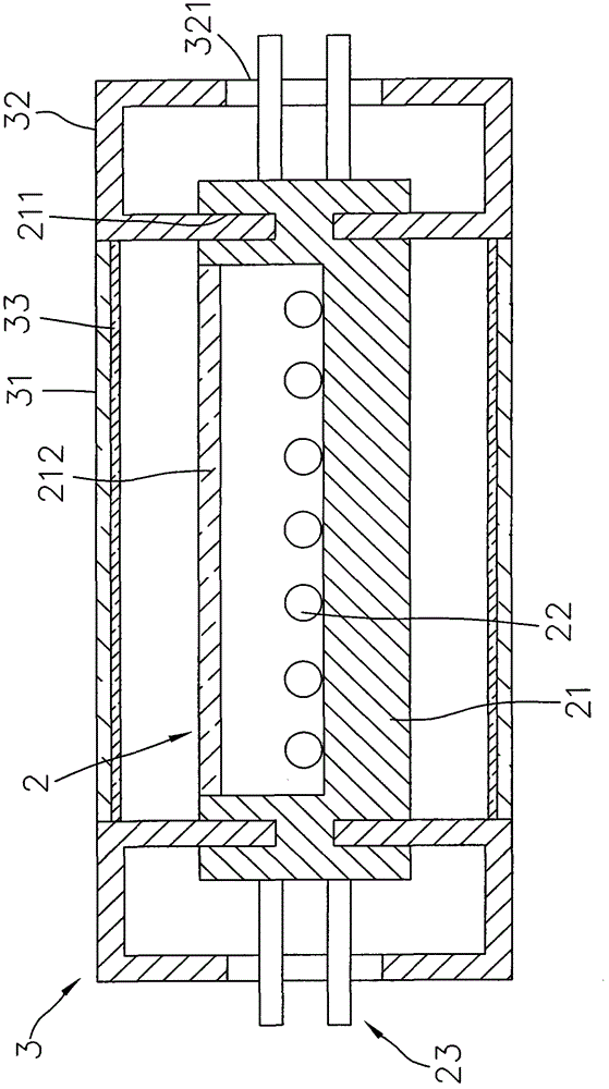
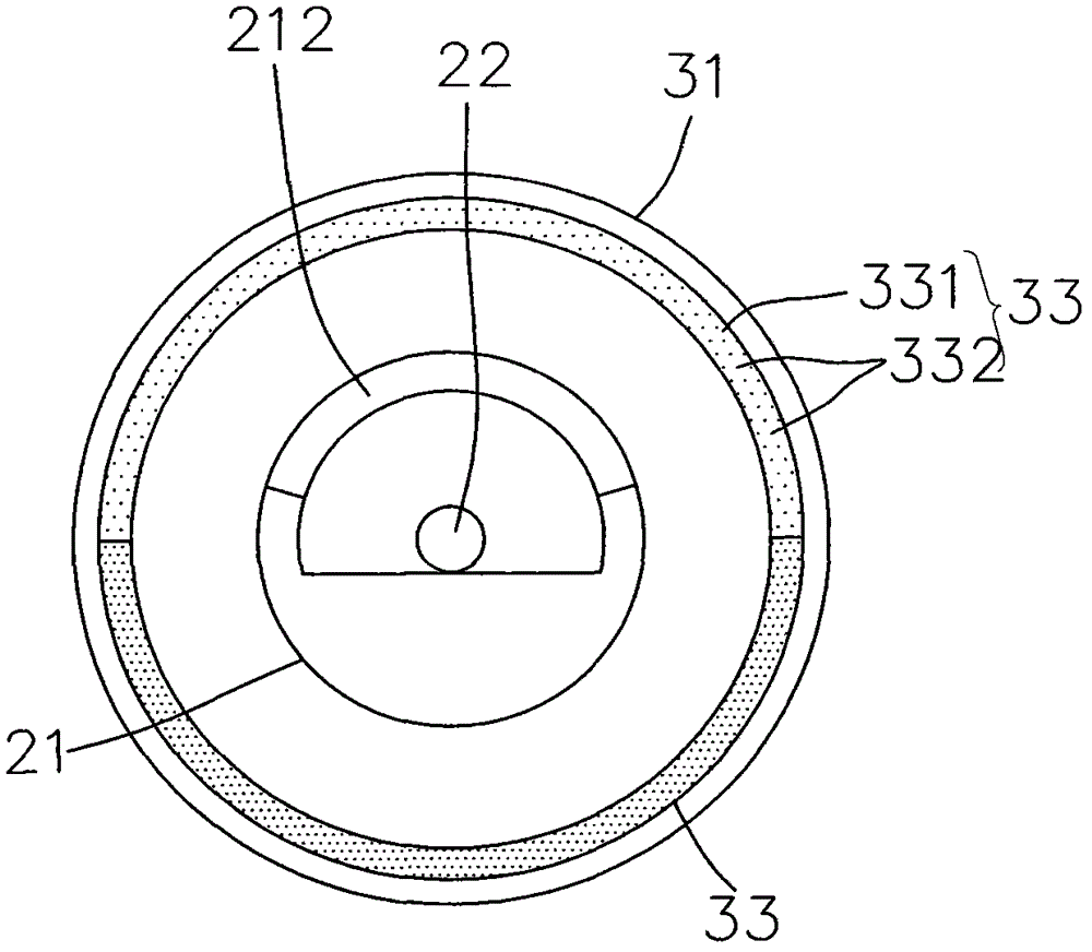
The present invention discloses a multi-stage color temperature regulation and control device, comprising an LED (Light Emitting Diode) structure and a casing structure; wherein, the LED structure comprises a tube body, a plurality of semiconductor light-emitting elements which are arranged in the tube body and produce light with a photoelectric effect, and two electrode elements which are arranged at two ends of the tube body and used for transmitting electric energy to the semiconductor light-emitting elements; the casing structure comprises a casing which is sleeved outside the tube body and rotates relative to the tube body, and a plurality of color temperature films which are adhered to the casing and can be re-excited to generate lights with different color temperatures when being irradiated by the lights emitted by the semiconductor light-emitting elements; when the casing is rotated relative to the tube body, the lights emitted by the semiconductor light-emitting elements irradiate the predetermined color temperature films, so that the lights with the predetermined color temperatures can be generated. By adopting the multi-stage color temperature regulation and control device of the present invention, a user only needs to rotate the casing, then the lights with the different color temperatures can be emitted by the same semiconductor light-emitting elements, thereby saving time for changing tubes at present and saving cost for manufacturing the light-emitting elements used for emitting the lights with the different color temperatures.

Description

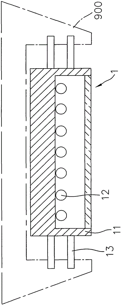
technical field [0001] The invention relates to a control device, in particular to a multi-stage color temperature control device. Background technique [0002] Compared with the old-fashioned mercury fluorescent lamps, the light-emitting diode grains are more energy-saving and have higher luminance. In addition, mercury fluorescent lamps tend to flicker after aging, causing discomfort and damage to the eyes; Mercury fluorescent lamps are replaced by light-emitting diode crystal grains as light-emitting elements in the lamp tube. [0003] see figure 1 As shown, the lamp tube 1 generally arranged on the lamp holder 900 includes a tube body 11, at least one light-emitting element 12 accommodated in the tube body 11, and a And the electrode device 13 that can transmit electric energy from the outside. The light emitting element 12 may be a light emitting diode die. [0004] When the light-emitting element 12 receives electric energy from the outside through the electrode de...

Claims


Application Information

Patent Timeline
IPC IPC(8): F21V14/08F21V9/40
Inventor 邹华龙
Owner LEXTAR ELECTRONICS CORP
Learn More