Method and device for measuring contact angle of ball bearing

A technology of measuring device and measuring method, which is applied in the direction of measuring device, mechanical bearing test, instrument, etc., can solve the problem of large contact angle error, and achieve the effect of convenient operation and accurate and reliable data

Active Publication Date: 2012-10-24
WUXI NO 2 BEARING
View PDF6 Cites 6 Cited by
  • Summary
  • Abstract
  • Description
  • Claims
  • Application Information

AI Technical Summary

Benefits of technology

This patented technology helps calculate how well two bearings work together by measuring their rotation speeds at different times during use. By comparing these measurements with each other, it can be used to accurately determine if there are any issues or defects between them. These results help companies make better-quality products more efficiently while also providing valuable insights into what they're doing right.

Problems solved by technology

This patented technical problem addressed in this patents relates to accurately measuring the contact angles (contact angles) on balls used in rolling-ball valve mechanisms that are designed specifically for high pressure applications such as hydraulic systems or nuclear power plants. Current methods involve testing each component separately before assembly into an overall system, but these techniques may result in errors due to factors like manufacturers' specifications and environmental conditions during operation.

Method used


Image

  • Method and device for measuring contact angle of ball bearing

Examples


Embodiment Construction

[0011] The specific embodiments of the present invention will be further described below in conjunction with the accompanying drawings.

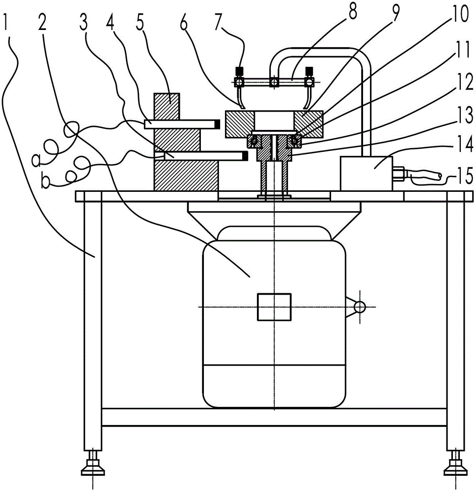
[0012] figure 1 Among them, including workbench 1, speed regulating motor 2, first photoelectric velocimeter 3, second photoelectric velocimeter 4, velocimeter fixing bracket 5, high-pressure gas nozzle 6, throttle valve 7, air pipe support 8, load block 9, Bearing inner ring 10, bearing cage 11, bearing outer ring 12, mandrel 13, air pipe support block 14, air intake pipe 15, etc.

[0013] Such as figure 1 As shown, a method for measuring the contact angle of a ball bearing provided by the present invention is as follows: the ball bearing includes a bearing inner ring 10, a bearing cage 11, steel balls and a bearing outer ring 12, and an axial preload is applied to the bearing outer ring 12, To ensure that the steel balls, the inner ring raceway and the outer ring raceway do not slip, rotate the bearing inner ring 10 and the bearing outer...


PUM


Abstract

The invention relates to a method and a device for measuring a contact angle of a ball bearing. The method comprises the steps of applying an axial preload on an outer ring of the bearing; rotating an inner ring of the bearing and the outer ring of the bearing in opposite directions; regulating the rotating speed of the inner ring of the bearing and the outer ring of the bearing so as to record the rotating speed of the inner ring of the bearing and the outer ring of the bearing when a bearing cage keeps relatively static; and computing the contact angle of the bearing according to the formula of alpha=arccos[Dcp(ni+ne)/Dw(ni-ne)]. The device provided by the invention comprises a working table; a speed regulating motor is installed on the working table; an output shaft of the speed regulating motor is provided with a mandrel; the upper part of the bearing is provided with a load block of the outer ring of the bearing for compacting the bearing; the upper part of the load block is provided with a load block driving device; and the working table is provided with a speed measuring device for measuring the rotating speed of the load block and the mandrel. According to the method and the device, the contact angle is computed through the rotating speed ratio of the inner ring of the bearing to the outer ring of the bearing when the differential speed is equal to 0; and the method is convenient to operate and accurate and reliable in a measuring result.

Description


Claims


Application Information

Patent Timeline
Owner WUXI NO 2 BEARING
Why Eureka
Try Eureka