
A current sampling circuit for intelligent power module

An intelligent power module and current sampling technology, which is applied in the direction of output power conversion device, AC power input conversion to DC power output, emergency protection circuit device, etc., can solve the problem of intelligent power module damage, failure of intelligent power module overcurrent protection, Explosion and other problems to achieve the effect of reducing the probability of explosion, eliminating fire hazards, and avoiding damage

Active Publication Date: 2015-10-28
美垦半导体技术有限公司
View PDF3 Cites 0 Cited by
  • Summary
  • Abstract
  • Description
  • Claims
  • Application Information

AI Technical Summary

Problems solved by technology

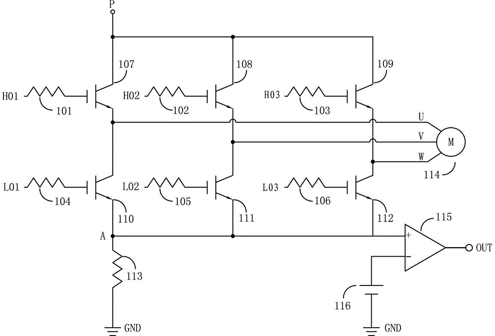
[0007] Because milliohm resistors are usually made of materials with a very small positive temperature coefficient, when the temperature of the smart power module rises sharply due to poor heat dissipation, the resistance value of the milliohm resistor will only increase slightly. When the temperature is abnormal, the protective effect can only be produced when the current reaches a fixed value; but the current capability of the power device decreases with the rise of the junction temperature, so when the temperature of the intelligent power module rises sharply, the current sampling circuit will not be able to advance Carry out overcurrent protection for the intelligent power module, causing the intelligent power module to be damaged due to abnormally high temperature, and will explode in severe cases

Method used


Image

  • A current sampling circuit for intelligent power module
  • A current sampling circuit for intelligent power module
  • A current sampling circuit for intelligent power module

Examples


Embodiment Construction

[0019] The present invention will be further described below in conjunction with the accompanying drawings and embodiments.

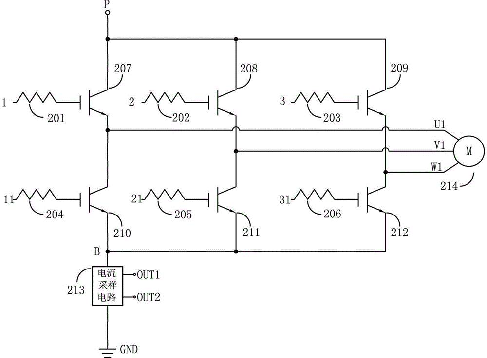
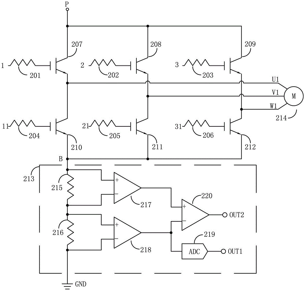
[0020] see Figure 2-Figure 3 , a current sampling circuit for an intelligent power module, including a first upper bridge arm 1, a second upper bridge arm 2, and a third upper bridge arm 3, and a first lower bridge arm 11 set corresponding to each upper bridge arm, The second lower bridge arm 21 and the third lower bridge arm 31, the upper and lower bridge arms are respectively connected to the gate of the corresponding IGBT tube through resistors, corresponding to the first upper resistor 201, the second upper resistor 202, and the third upper resistor 203 , the first lower resistor 204, the second lower resistor 205 and the third lower resistor 206; the collector phases of the IGBT tubes on each upper bridge arm are connected to the high voltage point P, and the collector phases of the IGBT tubes on each lower bridge arm are connected to the current ...


PUM


Abstract

A current sampling circuit for an intelligent power module comprises three upper bridge arms and three lower bridge arms which correspond to the upper bridge arms, wherein the upper bridge arms and the lower bridge arms are respectively connected with grid electrodes of corresponding insulated gate bipolar transistor (IGBT) tubes by resistors, a collector phase of the IGBT on each upper bridge arm is connected with a high-voltage point, a collector phase of the IGBT on each lower bridge arm is connected with an input end of the current sampling circuit, the current sampling circuit is provided with a first output end and a second output end as well as an input / output end grounding potential of the current sampling circuit. Besides the traditional over-current protection function, the current sampling circuit also has an over-temperature protection function, so that the intelligent power module can be guaranteed to work under a safety temperature; when the temperature is abnormal, even if the current is not abnormally extremely high, the intelligent power module can be stopped working, so that the damage of the intelligent power module under the high temperature and large current can be effectively avoided, the explosion possibility of the intelligent power module can be greatly reduced, the safety of subsequent circuits and devices can be guaranteed, and the fire potential danger of the device can be eliminated.

Description

technical field [0001] The invention relates to a current sampling circuit for an intelligent power module, in particular to current and temperature detection in an intelligent power module (IPM), and also to a compressor control technology for an inverter air conditioner. Background technique [0002] Intelligent Power Module, or IPM (Intelligent Power Module), is a power drive product that combines power electronics and integrated circuit technology. The intelligent power module integrates the power switching device and the high-voltage driving circuit, and has built-in fault detection circuits such as overvoltage, overcurrent and overheating. On the one hand, the intelligent power module receives the control signal from the MCU to drive the subsequent circuit to work, and on the other hand, it sends the system status detection signal back to the MCU. Compared with traditional discrete solutions, intelligent power modules have won an increasing market due to their advanta...

Claims


Application Information

Patent Timeline
Patent Type & Authority Patents(China)
IPC IPC(8): H02H7/122H02M7/521
Inventor 冯宇翔黄祥钧
Owner 美垦半导体技术有限公司
Learn More