Jet regulator

A technology of jet regulator and outflow end, which is applied in indoor sanitary pipeline installations, water supply installations, buildings, etc., and can solve the problem that the jet regulator is not described in detail

Active Publication Date: 2014-06-25
NEOPERL
View PDF6 Cites 3 Cited by
  • Summary
  • Abstract
  • Description
  • Claims
  • Application Information

AI Technical Summary

Problems solved by technology

The other components of this known jet regulator are not described in detail in DE 101 62 662 A1

Method used


Image

  • Jet regulator
  • Jet regulator
  • Jet regulator

Examples


Embodiment Construction

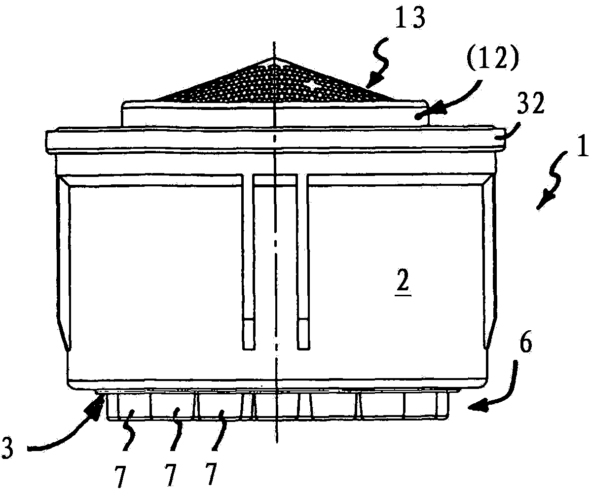
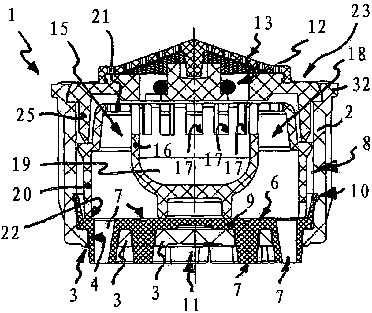
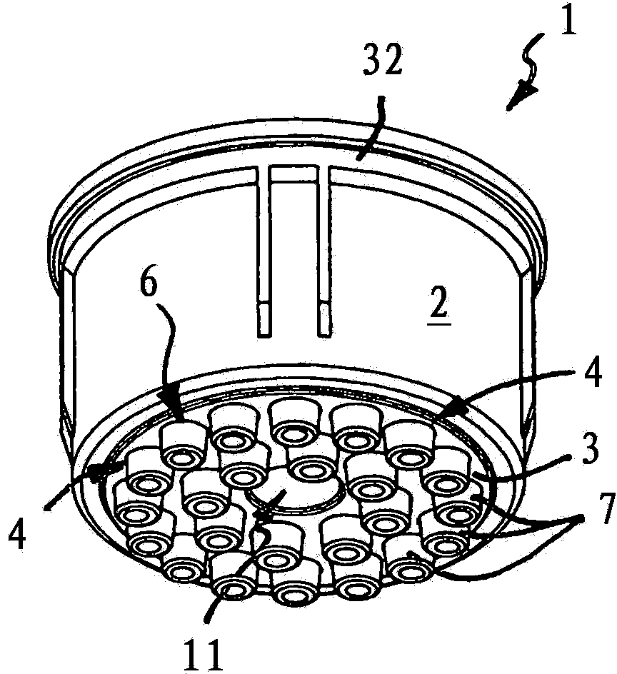
[0043] exist Figures 1 to 17 The various embodiments 1, 5, 30, 31 of jet regulators are shown in the figure, from which the water is to flow out as a shower-like water jet formed from a plurality of individual jets. The substantially pot-shaped jet regulator housing 2 has a plurality of perforations 4 on its outflow end face 3 forming the pot bottom of the pot-shaped jet regulator housing 2 .

[0044] The jet regulators 1 , 5 , 30 and 31 are assigned a separate insert 6 which engages in the housing interior as far as the outflow end face 3 . The insert 6 has a plurality of hose-shaped nozzles 7 which are intended to generate a plurality of individual jets which preferably flow separately visibly. The nozzles 7 each pass through a perforation 4 on the outflow end face of the jet regulator housing 2 and protrude with their free nozzle end regions beyond the outflow end face 3 of the jet regulator 1 , 5 , 30 , 31 .

[0045] The previously known jet regulators 1 , 5 , 30 , 31 a...


PUM


Abstract

A jet regulator (1) including a two-part jet-regulator housing (2), the outlet end face (3) of which has multiple passages (4), a pot-shaped inlay (6) that is inserted into the housing interior (2) until it reaches the outlet end face (3) and that has multiple tubular spray nozzles (7), each of which penetrates a passage (4) on the outlet end face of the jet regulator housing (2) and the free spray-nozzle region of which protrudes beyond the outlet end face (3) of the jet regulator (1, 5). The jet regulator also includes an insert (8) that is inserted in the housing interior and the position of the inlay part (6) is secured in an axial direction between the insert, the second housing part and the outlet end face (3).

Description

technical field [0001] The invention relates to a jet regulator. Background technique [0002] A jet regulator of the type mentioned at the outset is known from DE 44 36 193 A1, which has a jet regulator housing which has a plurality of perforations on its outflow end face. The known jet regulator is equipped with an insert which engages in the housing interior of the jet regulator housing as far as the outflow end face and which has a plurality of tube-shaped tubes made of soft elastic material. nozzles, which each pass through a perforation on the outflow end face of the jet regulator housing. The free nozzle end regions protrude from the outflow end face of the jet regulator with their free nozzle end regions, each passing through a perforated nozzle on the outflow end face, so that these protruding nozzle ends can be deformed by the user by stroking them with the hand, so that Possible crusts formed of calcium etc. are easily removed. In order to fasten the disk-shape...

Claims


Application Information

Patent Timeline
Patent Type & Authority Patents(China)
IPC IPC(8): E03C1/08
CPCE03C1/08E03C2201/70
Inventor G·布卢姆
Owner NEOPERL
Why Eureka
Try Eureka