Device and method for fixing an impeller to a shaft

A technology of impeller and fixed parts, which is applied to parts of pumping devices for elastic fluids, non-variable displacement pumps, machines/engines, etc., can solve the problems of labor-intensive, high-cost, and time-consuming processing technology for threaded connections.

Inactive Publication Date: 2007-09-05
ROBERT BOSCH GMBH
View PDF3 Cites 3 Cited by
  • Summary
  • Abstract
  • Description
  • Claims
  • Application Information

AI Technical Summary

Problems solved by technology

However, screw connections are time-consuming and therefore very expensive in terms of production technology
In addition, this threaded connection requires a complex clamp construction

Method used


Image

  • Device and method for fixing an impeller to a shaft
  • Device and method for fixing an impeller to a shaft
  • Device and method for fixing an impeller to a shaft

Examples


Embodiment Construction

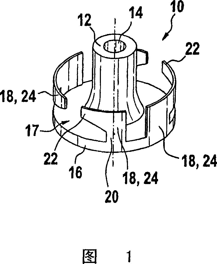
[0031] FIG. 1 shows a possible embodiment of a clip 10 according to the invention for fastening an impeller on a shaft. The preferably one-piece clamp 10 is extruded from steel sheet, but can also be made of other metallic or non-metallic materials, such as plastic. In this case the clip is advantageously produced by injection molding.

[0032]The clip 10 has an essentially cylindrical hub 12 in its center, which has a through-opening 14 for receiving a shaft. The clamp 10 is fixed on the shaft, such as the drive shaft of the motor, by means of the hub 12 , such as being compressed or shrink-fitted. In an alternative embodiment of the device according to the invention, instead of the through hole 14 , it is also possible, for example, for the clip to have a blind hole in the hub for receiving the shaft.

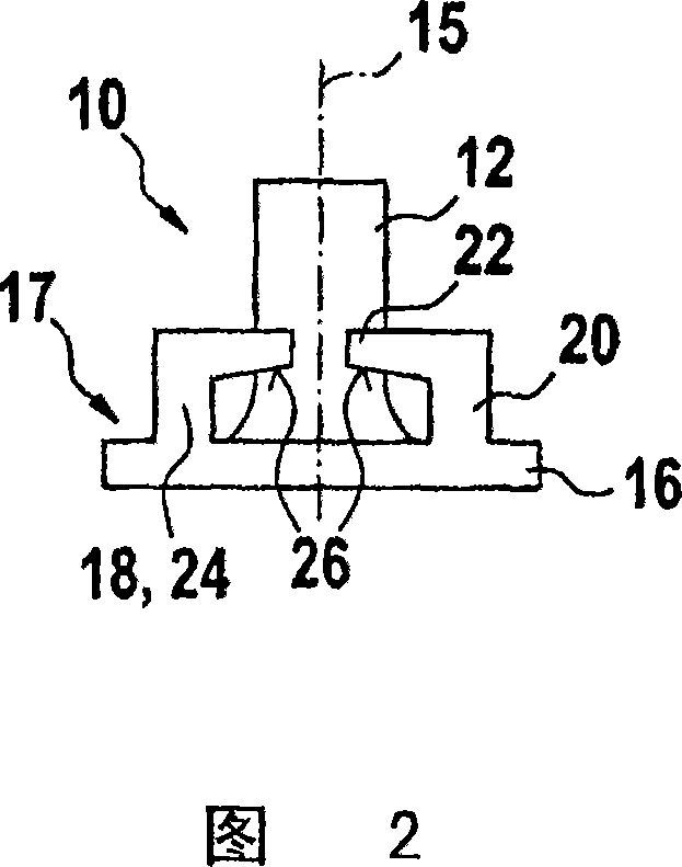
[0033] At its axial end corresponding to the lower end in FIG. 1 , the clip 10 according to the exemplary embodiment in FIG. 1 has a plate-shaped widening 16 which is forme...


PUM


Abstract

The invention relates to a device and a method for fixing an impeller, especially a blower impeller (30), to a shaft, especially a drive shaft of an electric motor. Said device comprises a driving element (10) that can be applied to the shaft in a rotationally fixed manner in order to transfer a rotational movement of the shaft to the impeller (30). The driving element (10) comprises a plurality of essentially axially embodied holding elements (18,24) projecting from the driving element, said holding elements at least partially penetrating a hub part (32) of the impeller (30). According to the invention, the holding elements (18,24) of the driving element (10) engage behind the hub part (32) by deformation.

Description

[0001] The invention relates to a device for fastening an impeller on a shaft according to the preamble of claim 1 . The invention also relates to a method for fastening an impeller on a shaft according to the preamble of claim 13 . Background technique [0002] Numerous methods are known from the prior art by which an impeller, such as a fan wheel, can be fastened on a shaft, in particular an electric motor shaft. For this purpose, for example, a bushing cast in the impeller, the bushing pressed onto the shaft or a separate metal sleeve pressed onto the shaft is used for this, the impeller being fastened to this metal sleeve by means of springs or screws. [0003] In devices known from the prior art, the impeller, which is mostly made of plastic, is mounted on the drive shaft, for example the motor shaft, by means of a clamp via a form-fit connection. A corresponding profile corresponding to the clip is located on the impeller to be driven, whereby a synchronous action is ac...

Claims


Application Information

Patent Timeline
Patent Type & Authority Applications(China)
IPC IPC(8): F04D29/26F04D29/32
CPCF04D29/263F04D29/329
Inventor F·科普夫
Owner ROBERT BOSCH GMBH
Why Eureka
Try Eureka