Method and device for threading a web in the reeling of a paper or board web

a technology of paper or board webs and threading devices, which is applied in the field of reeling of paper webs, can solve the problems of random amount of loose strips, inability to remove the air flow of the boundary layer produced by the rotating drum, and inability to remove the air flow of the rotating drum, etc., and achieve the effect of reliably threading operation

Inactive Publication Date: 2005-09-22
VALMET TECH INC
View PDF7 Cites 3 Cited by
  • Summary
  • Abstract
  • Description
  • Claims
  • Application Information

AI Technical Summary

Benefits of technology

[0008] A particular object of the invention is to create an arrangement which, when used, enables the tail strip to adhere very well to the reeling drum and ensures that the tail strip is guided to the reeling nip.
[0009] A further object of the invention is to provide an arrangement which enables the tail strip to be positioned in the suction zone of the reeling drum both in the circumferential direction and in the lateral direction.
[0010] In accordance with the invention, a suction zone is arranged in connection with a reeling drum, which suction zone extends over the entire circumference of the drum and is located in the area of the web in the width direction of the web, i.e. in the longitudinal direction of the drum, so that the tail strip of the web will also be positioned in the suction zone area also in the lateral direction without a transfer accomplished by means of blowings or the like. The strip is sought to be brought to the holding point as tight as possible, that is without looseness.
[0011] In accordance with an advantageous feature of the arrangement of the invention, the apertures for achieving a suction effect, i.e. suction holes, are arranged at the bottom of the grooves of a grooved drum, most appropriately with close spacing. By this means, the boundary layers produced by the rotating drum and the moving web can be eliminated or reduced so as to be insignificant, with the result that the threading operation takes place reliably.
[0012] In an arrangement in accordance with an advantageous embodiment of the invention, the boundary layer produced during one revolution of the reeling drum is removed during the same revolution and, at the same time, the air amount carried with the tail strip is sucked. In that connection, the air amount sucked through the suction zone preferably exceeds the air amount carried in the boundary layer of the drum, so that by means of this so-called oversucking of the boundary layer it is assured that a vacuum effect, i.e. a lower static pressure, extends beyond the boundary layer, whereby the tail strip can be brought closer to the drum and caused to adhere to the surface of the reeling drum. The air carried with the tail strip is also sucked by means of this so-called oversucking.
[0013] In the arrangement in accordance with the invention, the tail strip can be made to adhere to the reeling drum in a reliable manner and the tail strip goes into the nip in a reliable manner. When, in accordance with the invention, the suction zone is disposed within the web area in the width direction of the web, the tail strip can be brought to the suction zone of the reeling drum without a lateral shift, which means that no separate means are needed for moving the tail strip in the lateral direction. In addition, in the arrangement in accordance with the invention, the tail strip is always positioned in the suction zone in the circumferential direction because the suction zone extends over the entire circumference.

Problems solved by technology

In known arrangements in which the suction zone is formed into a sector, it is hardly at all possible to remove the boundary layer air flow produced by the rotating drum.
In many cases, the location of the suction zone sector is also not optimal on the circumference of the drum because the tail strip typically misses the area of the suction sector in the threading operation.
The strip may also be directed towards the middle of the machine and it may slip into the nip from some unpredictable point.
This leads to a random amount of loose strip.
The tightening of the loose strip lengthens the time taken by threading unnecessarily.
In many cases it does not even succeed, but breaks when it flaps and flutters into other structures of the machine.
After unsuccessful threading attempts, the threading path must be cleared to remove broken tail strips in order that new attempts may be made, which in turn further increases the threading time unnecessarily.
This known arrangement does not teach threading of a web.

Method used


Image

  • Method and device for threading a web in the reeling of a paper or board web
  • Method and device for threading a web in the reeling of a paper or board web
  • Method and device for threading a web in the reeling of a paper or board web

Examples


Embodiment Construction

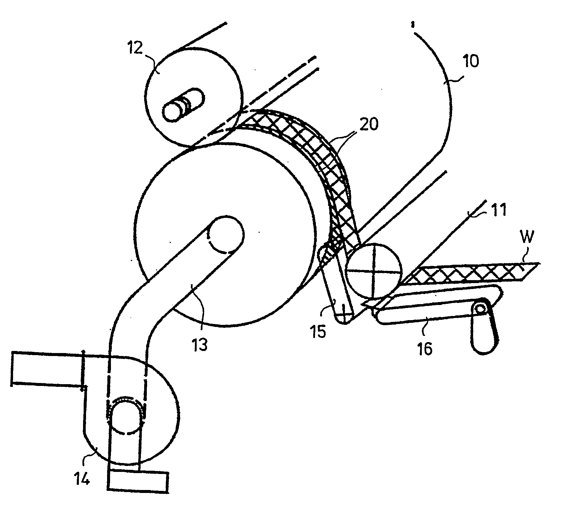
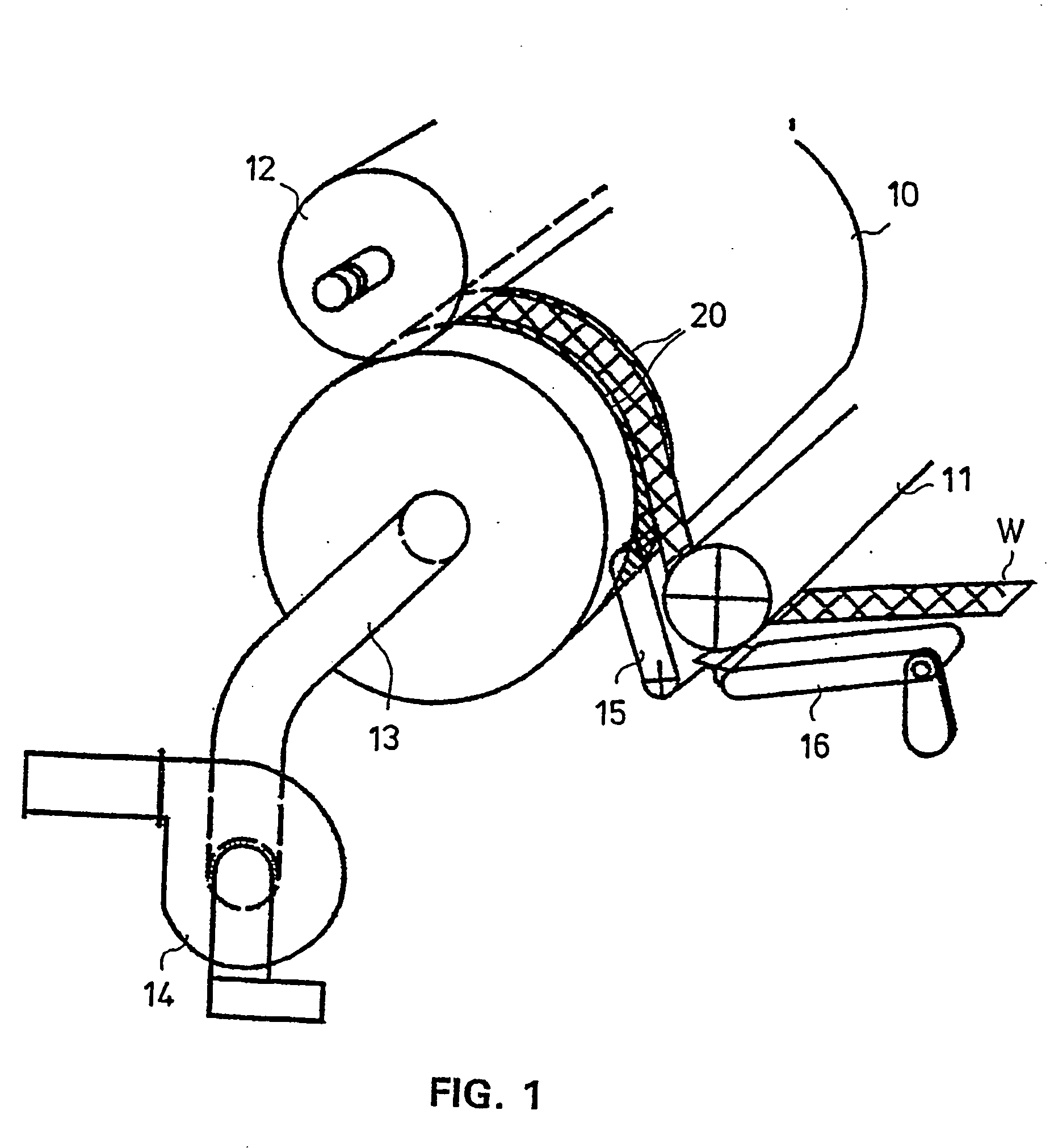
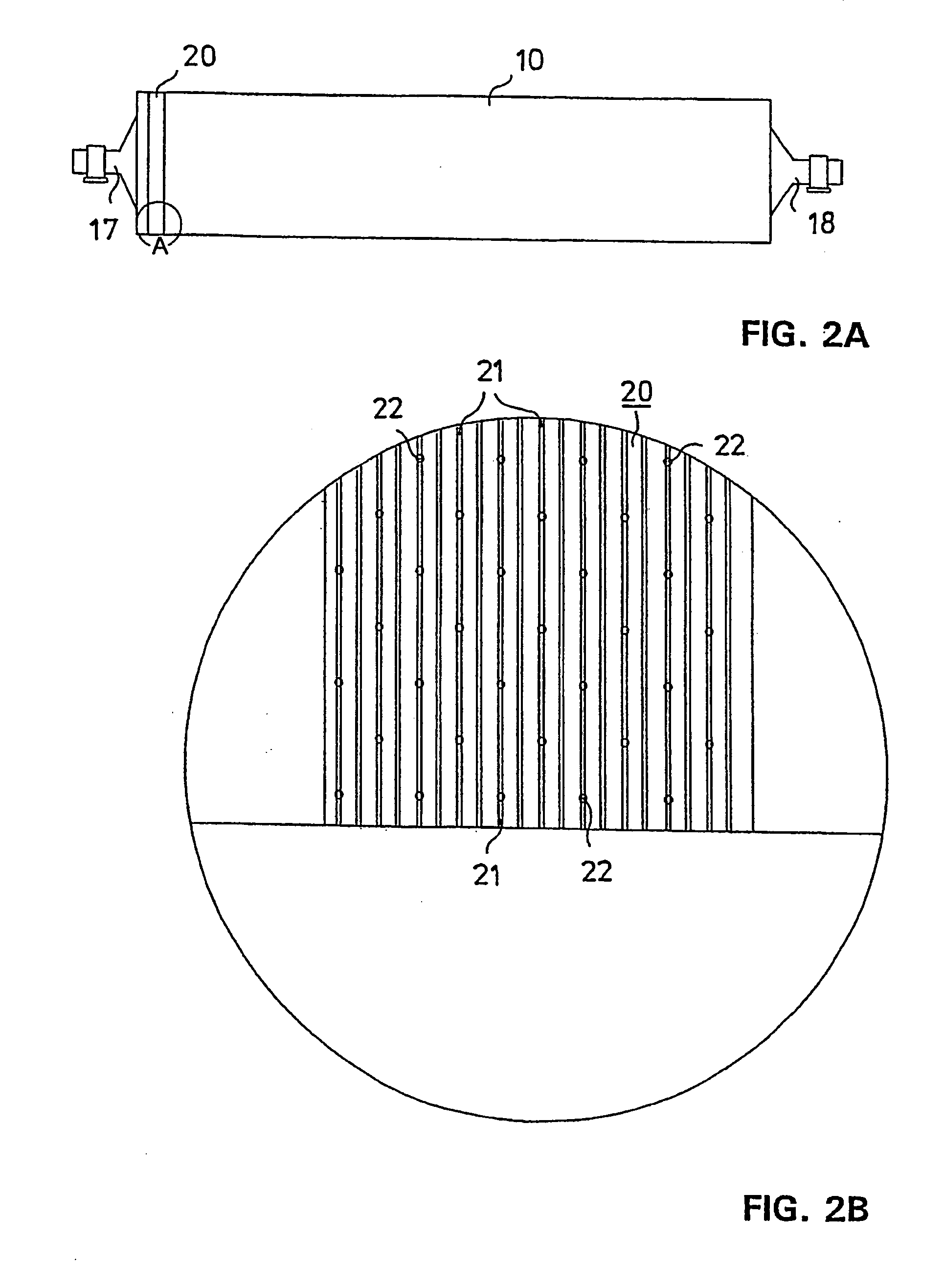
[0023] In the schematic view of the embodiment shown in FIG. 1, a tail strip W is passed in a threading situation in a reel-up via a paper guide roll 11 or equivalent to a reeling drum 10, on which it adheres to the surface of the reeling drum 10 by means of a suction zone 20 of the reeling drum 10 and by means of the suction zone 20 the web is passed to a reeling nip between the reeling drum 10 and a reel spool 12, from which nip the tail strip is turned onto the reel spool 12 to start a new reeling operation. Belt conveyors 15, 16, the operation of which is in itself known by a person skilled in the art, are arranged in the vicinity of the paper guide roll 11 for conducting the tail strip W. A suction tube 13 leads from one end of the reeling drum 10 to a blower 14 to produce a suction zone in the suction zone 20 by means of suction provided from inside the reeling drum. The suction zone 20 is placed in the reeling drum 10 in the longitudinal direction of the reeling drum 10, i.e....


PUM

PropertyMeasurementUnit
circumferenceaaaaaaaaaa
diameteraaaaaaaaaa
diameteraaaaaaaaaa

Abstract

A web is threaded in the reeling of a paper or board web, by passing a web tail strip (W) into a reeling nip between a reeling drum (10) and a reel spool (12), on which a web roll is formed. The tail strip (W) is passed into the reeling nip by a suction zone (20) which extends substantially around the entire reeling drum circumference and is (10) in an area where a full-width web runs during reeling, so that the tail strip (w) can be conducted directly along the suction zone (20). The suction zone (20) is placed in the longitudinal direction of the reeling drum (10), i.e. in the width direction of the web.

Description

CROSS REFERENCES TO RELATED APPLICATIONS [0001] This application is a U.S. national stage application of international application No. PCT / FI2003 / 000595, filed Aug. 7, 2003, the disclosure of which is incorporated by reference herein and claims priority on Finnish Application No. 20021459, Filed Aug. 9, 2002. STATEMENT AS TO RIGHTS TO INVENTIONS MADE UNDER FEDERALLY SPONSORED RESEARCH AND DEVELOPMENT [0002] Not applicable. BACKGROUND OF THE INVENTION [0003] As known in the prior art, in connection with the reeling of a paper web, a reeling drum is used which is provided with suction zones of the sector type, i.e. suction takes place through holes situated in a suction drum shell only in part of the circumference of the drum in the area of a certain sector. One prior-art arrangement in the reeling of a paper web, using a reeling drum provided with a suction zone sector, is disclosed in FI patent 74446. In known arrangements in which the suction zone is formed into a sector, it is har...

Claims


Application Information

Patent Timeline
Patent Type & Authority Applications(United States)
IPC IPC(8): B65H18/26B65H19/28D21F7/00D21G9/00
CPCB65H19/28B65H2301/522B65H2301/543D21G9/0063B65H2408/236B65H2801/84B65H2406/33
Inventor AHVENNIEMI, VESAWIDELL, KENNETHKASULA, HANNULAINE, SEPPOFAGERSTROM, BO
Owner VALMET TECH INC
Why Eureka
Try Eureka