Lateral pressure type self-locking device

A technology of self-locking devices and shells, applied in safety belts, life-saving equipment, etc., can solve problems such as safety hazards and increase the workload of operators, and achieve the effect of reducing safety hazards and reducing additional operations

Active Publication Date: 2014-11-19
CHINA ENERGY ENG GRP GUANGDONG ELECTRIC POWER DESIGN INST CO LTD
View PDF5 Cites 0 Cited by
  • Summary
  • Abstract
  • Description
  • Claims
  • Application Information

AI Technical Summary

Problems solved by technology

Because this type of self-locking device requires additional auxiliary operations when passing through the connector, which increases the workload of the operator and also brings potential safety hazards

Method used


Image

  • Lateral pressure type self-locking device
  • Lateral pressure type self-locking device
  • Lateral pressure type self-locking device

Examples


Embodiment Construction

[0032] Embodiments of the present invention are described in detail below:

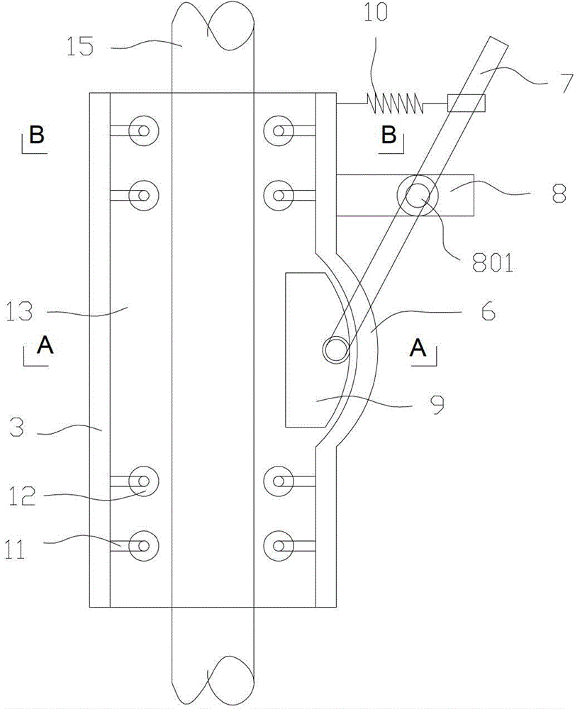
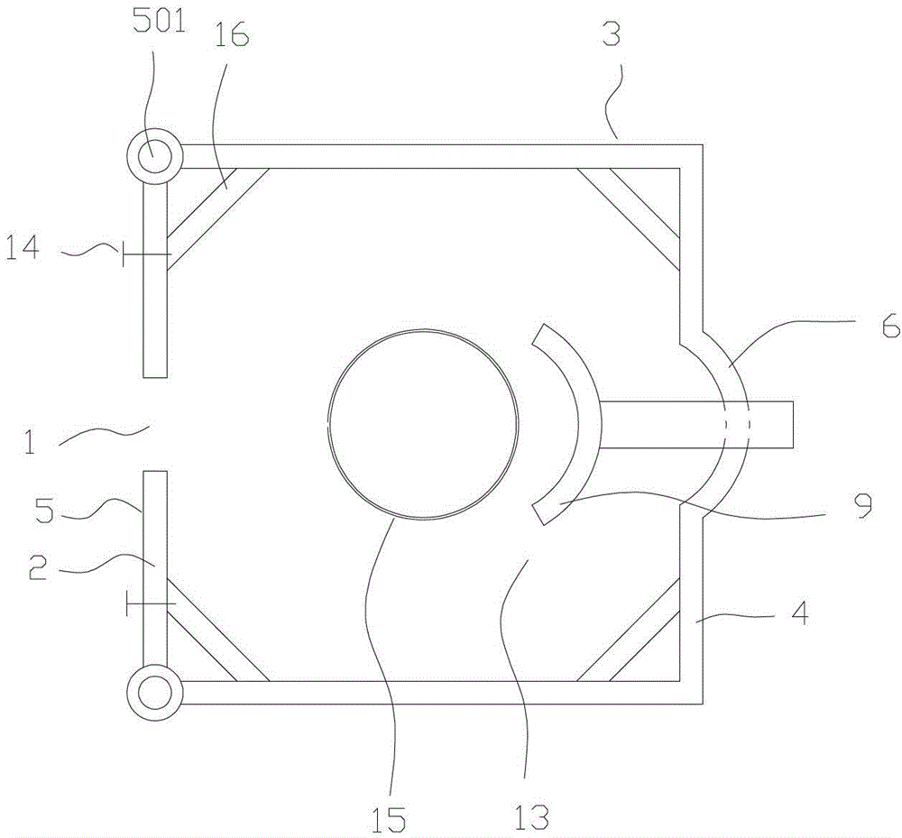
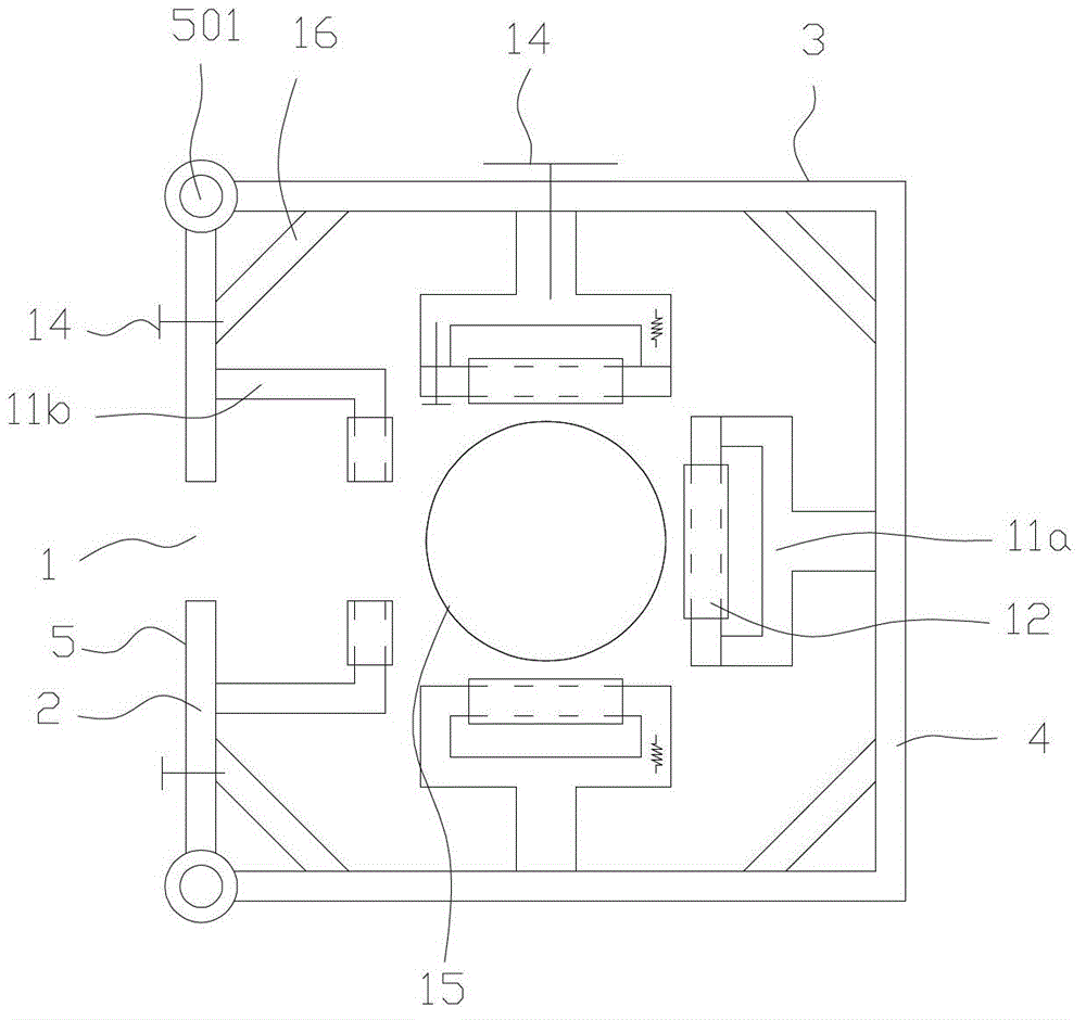
[0033] Such as figure 2 with Figure 4 As shown, a side pressure self-locking device includes a housing 3, and the housing 3 is provided with a fixed housing wall 4 and a movable housing wall 5, and the fixed housing wall 4 and the movable housing wall 5 are arranged in the housing 3. A cavity 13 is formed in the middle part, and a guide groove 1 is provided on the movable shell wall 5, and the upper and lower ends of the guide groove 1 are respectively provided with guide openings 101, and the guide groove 1 communicates with the above-mentioned cavity 13.

[0034] Wherein, the movable shell wall 5 includes two movable trough plates 2, one edge of the two movable trough plates 2 is provided with a rotating shaft 501, and the edge is connected to the fixed shell wall 4 through the rotating shaft 501, and the other The edge forms the guide groove 1 described above. The guide port 101 has an arc-sha...


PUM


Abstract

The invention discloses a lateral pressure type self-locking device which comprises a shell, wherein the shell is provided with a fixed shell wall and a movable shell wall; the fixed shell wall and the movable shell wall are enclosed to form a cavity at the middle part of the shell; the movable shell wall is provided with a guide groove; guide holes are formed respectively arranged at the upper end and the lower end of the guide groove; the guide groove is communicated with the cavity; and a bracket is also arranged on the inner wall of the shell and is provided with a rolling wheel shaft. The lateral pressure type self-locking device has the advantages that a connector can successfully pass through the lateral pressure type self-locking device without additional auxiliary operation, so that the safety hidden dangers are lowered; and in addition, the lateral pressure type self-locking device is contacted with a steel strand in a rolling way, so that the motion ability of the lateral pressure type self-locking device is improved, and the abrasion of the steel strand is also reduced.

Description

technical field [0001] The invention relates to a steel strand wire fall prevention device, in particular to a self-locking device. Background technique [0002] Existing anti-falling devices for steel strands usually include components such as laces, safety ropes, connectors, and self-locking devices, wherein the self-locking device is the core component of this type of device. When this type of self-locking device passes through the connector, it usually requires manual additional actions to pull the steel strand out of the connector, and then pull the steel strand back into the connector after the self-locking device passes through smoothly. Because this type of self-locking device requires additional auxiliary operations when passing through the connector, which increases the workload of the operator and also brings potential safety hazards. Contents of the invention [0003] Based on this, the present invention overcomes the defects of the prior art and provides a la...

Claims


Application Information

Patent Timeline
Patent Type & Authority Patents(China)
IPC IPC(8): A62B35/00
Inventor 何运祥徐力谢荣坤李敏生黄炳权肖志军杨雅芬徐瑞崔磊梁德飞王蜂岚章冕颜耀麟黄龙湘
Owner CHINA ENERGY ENG GRP GUANGDONG ELECTRIC POWER DESIGN INST CO LTD
Why Eureka
Try Eureka