Connection method and structure for inner battery box and outer battery box

A connection method and connection structure technology, which is applied in the field of battery box replacement, can solve the problems of connection components burning, unfavorable standardization and installation, and connector detachment, so as to improve production and installation efficiency, wide versatility and interchangeability, Ease of production and installation

Active Publication Date: 2012-10-31
GUIYANG PUTIAN LOGISTICS TECH +1
View PDF8 Cites 5 Cited by
  • Summary
  • Abstract
  • Description
  • Claims
  • Application Information

AI Technical Summary

Problems solved by technology

[0003]At present, the connection components on electric vehicles are basically planar connections, and the planar connectors mainly squeeze the working surfaces of the inner battery box and the outer battery box Pressed together, there is a flexible connection between the two without forming a rigid whole. When the external force generated by the bumping and inertial extrusion of the electric vehicle acts on the connecting components, relative motion or friction will occur between the planar connectors. In severe cases It will cause instant separation between the connectors, resulting in virtual connection. For high-voltage electrodes, it is easy to generate discharge phenomenon, causing the electrodes to burn, which seriously affects the normal operation of the vehicle.
Because there is no good dustproof and waterproof measures for plane connection, there will be dust or adhesive moisture between the connectors, and discharge may occur at any time, causing partial or overall burning of the connected components and affecting the normal operation of the entire vehicle
In addition, the existing planar connection mainly adopts a decentralized connection method, the installation size is large, and the relative position between the connection components is difficult to ensure, which brings certain difficulties to the processing and is not conducive to the standardization of production and installation.

Method used


Image

  • Connection method and structure for inner battery box and outer battery box
  • Connection method and structure for inner battery box and outer battery box
  • Connection method and structure for inner battery box and outer battery box

Examples


Embodiment Construction

[0025] The present invention will be further described in detail below in conjunction with the accompanying drawings and embodiments, but not as any limitation to the present invention.

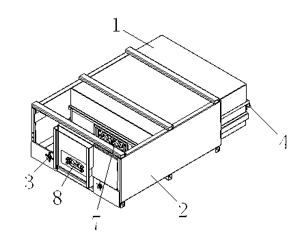
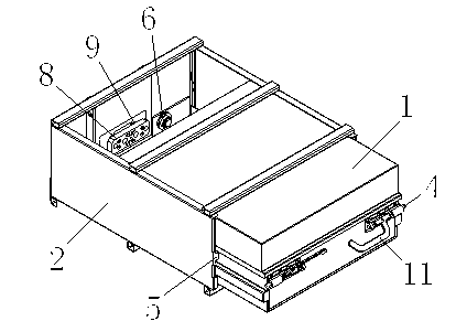
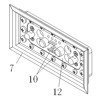
[0026] Embodiments of the present invention: the principle of the connection method of a battery inner and outer box of the present invention is as follows, as figure 1 and figure 2 As shown, the battery inner box 1 and the battery outer box 2 are connected in a drawer type; the front end of the battery inner box 1 and the battery outer box 2 generate pre-pressure on the battery inner box 1 through the elastic limit seat 3; the battery inner box 1 The locking tongue 4 on the battery outer box 2 is inserted into the lock hole 5; to ensure that the relative position between the battery inner box 1 and the battery outer box 2 does not shift; the bottom of the elastic limit seat 3 is processed with a rigid limit bit station 6 (see figure 2 and Figure 7 ), to prevent excessive extrus...


PUM


Abstract

The invention discloses a connection method and structure for an inner battery box and an outer battery box. In the invention, the inner battery box (1) is connected with the outer battery box (2) in a drawer manner; an elastic limited seat generates pre-pressure to the inner battery box (1) between the front end of the inner battery box (1) and the outer battery box (2); and a bolt (4) on the inner battery box (1) is connected with a keyhole (5) in the outer battery box (2) in an inserting manner, so as to ensure no displacement of the relative positions of the inner battery box (1) and the outer battery box (2). The connection method and structure can improve the connection reliability between the inner battery box and the outer battery box, and avoid sudden breakaway and electric discharge to result in connector burning to affect the normal operation of a vehicle due to relative movement and friction between the inner battery box and the outer battery box.

Description

technical field [0001] The invention relates to a connection method and structure of an inner and outer box of a battery, and belongs to the technical field of battery box replacement for electric vehicles. Background technique [0002] The battery is the main power unit of the electric vehicle, and the reliability of the battery connection plays a vital role in the operation safety of the electric vehicle. The battery outer box is installed on the electric vehicle, and the battery pack is contained in the battery inner box. Both the battery inner box and the battery outer box are equipped with an electrical connection group, and the battery inner box and the battery outer box are connected through a connection assembly. Since the electric vehicle is a moving carrier, the bumps of the electric vehicle during the movement and the inertial extrusion of the electric vehicle during acceleration and braking will affect the reliability of the connection components between the bat...

Claims


Application Information

Patent Timeline
Patent Type & Authority Applications(China)
IPC IPC(8): H01M2/10
CPCY02E60/12Y02E60/10
Inventor 王震坡李军申健初胡寸魁
Owner GUIYANG PUTIAN LOGISTICS TECH
Why Eureka
Try Eureka