
Cable terminal crimping machine

A terminal crimping machine and terminal crimping technology, which is applied in the direction of connection, connection through deformation, line/collector parts, etc., can solve the problems of low work efficiency, low efficiency of terminal crimping, large errors, etc.

Inactive Publication Date: 2012-10-31
ZHONGSHAN JINSHENG AUTOMATION MACHINERY
View PDF6 Cites 15 Cited by
  • Summary
  • Abstract
  • Description
  • Claims
  • Application Information

AI Technical Summary

Problems solved by technology

[0002] With the development of the electronics industry, in order to improve production efficiency, the division of labor in manufacturing is becoming more and more detailed. At present, there is an industry specializing in terminal crimping, while traditional terminal crimping needs to be done manually from wire feeding to terminal crimping. The efficiency is low and the error is large. Although there are some machines specially used for crimping terminals, most of these terminal crimping machines are for terminal crimping of a single wire. When it is necessary to crimp the terminal of the cable, Both require manual crimping, or manual crimping on the terminal crimping machine after branching. The operation is very troublesome, and the efficiency of terminal crimping is very low.

Method used


Image

  • Cable terminal crimping machine
  • Cable terminal crimping machine
  • Cable terminal crimping machine

Examples


Embodiment Construction

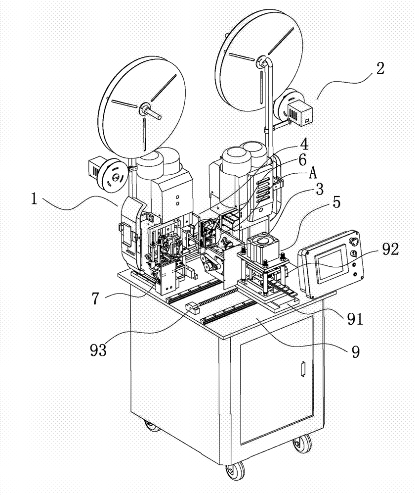
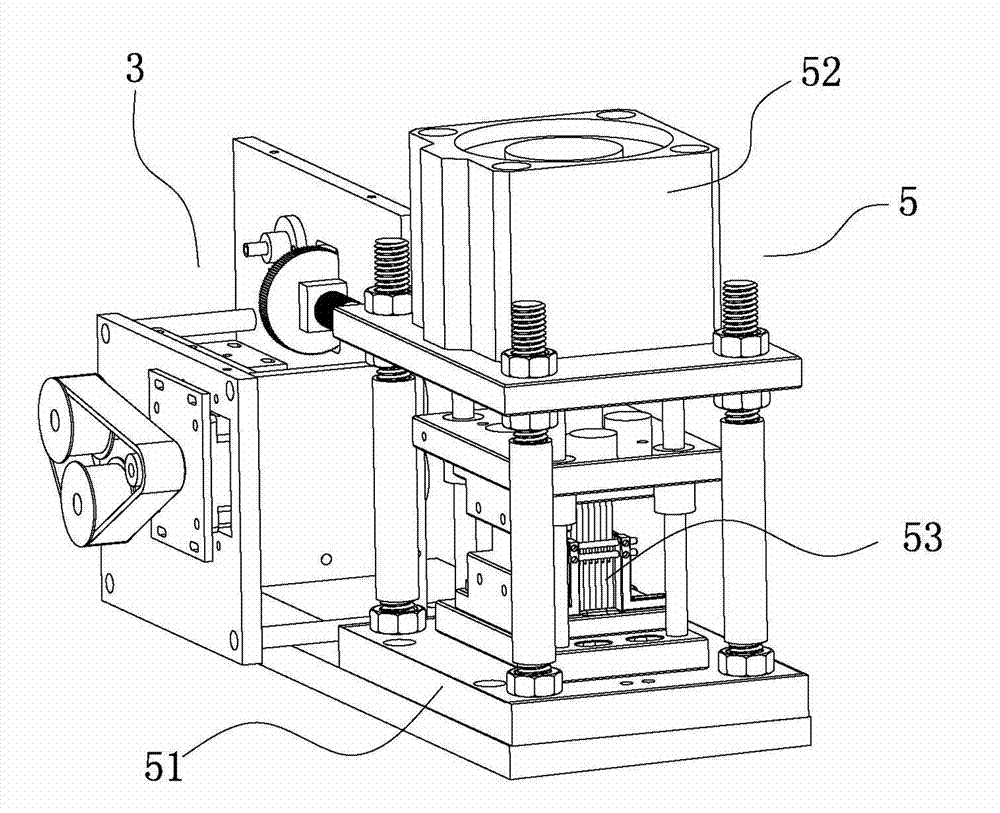
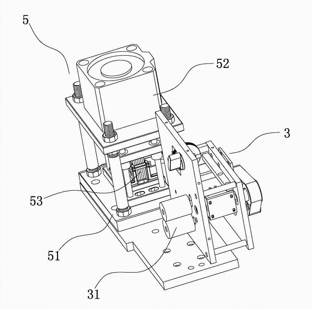
[0026] refer to Figure 1 to Figure 8 , Figure 1 to Figure 8 It is a structural schematic diagram of a specific embodiment of the present invention. As shown in the figure, a cable terminal crimping machine includes a frame 9, a wire feeding device arranged on the frame 9, a wire stripping device 6, and a terminal crimping device , the branching device 5, wherein the terminal crimping device is provided with two groups, which are the first terminal crimping device 1 and the second terminal crimping device 2 respectively, and the wire feeding device is provided with two groups, which are respectively the first terminal crimping device 1 and the second terminal crimping device 2. The first wire feeding device 3 corresponding to the terminal crimping device 1, the second wire feeding device 4 corresponding to the second terminal crimping device 2, and the wire stripping device 6 are compatible with the first wire feeding device 3 and the second wire feeding device 4 Correspondi...


PUM


Abstract

The invention discloses a cable terminal crimping machine, comprising a rack, a cable feeding device arranged on the rack, a cable stripping device and a terminal crimping device, wherein the rack is provided with a cable dispersing device capable of dispersing cables; and the terminal crimping device is provided with a cable drawing device capable of drawing out the dispersed cables one by one. The cables are dispersed by the cable dispersing device, then are fed by the cable feeding device, then are stripping by the cable stripping device, and fiannly are conveyed to the terminal crimping device; in a terminal crimping process, the cable drawing device is used for sequentially separating the dispersed cables one by one, and the terminal crimping operation of single lead is carried out by the terminal crimping device so as to finish the terminal crimping of the whole cable; the whole terminal crimping process is automatically finished by the machine and does not need manual operation, and the terminal crimping efficiency is high; and the cable terminal crimping machine disclosed by the invention can be improved on the basis of the conventional terminal crimping machine, so that the generality of parts is high, the manufacturing cost is low, and the maintenance is very convenient.

Description

technical field [0001] The invention relates to a cable terminal crimping machine. Background technique [0002] With the development of the electronics industry, in order to improve production efficiency, the division of labor in manufacturing is becoming more and more detailed. At present, there is an industry specializing in terminal crimping, while traditional terminal crimping needs to be done manually from wire feeding to terminal crimping. The efficiency is low and the error is large. Although there are some machines specially used for crimping terminals, most of these terminal crimping machines are for terminal crimping of a single wire. When it is necessary to crimp the terminal of the cable, Both require manual crimping, or crimping on a terminal crimping machine after manual branching. The operation is very troublesome, and the efficiency of terminal crimping is very low. Contents of the invention [0003] In order to overcome the deficiencies of the prior art,...

Claims


Application Information

Patent Timeline
IPC IPC(8): H01R43/05H01R43/052
Inventor 李建和
Owner ZHONGSHAN JINSHENG AUTOMATION MACHINERY
Learn More