AI technical title is built by PatSnap AI team. It summarizes the technical point description of the patent document.
A pressure sensor, fiber grating technology, applied in the direction of fluid pressure measurement, measurement of fluid pressure, instruments, etc. using optical methods, can solve the problems of temperature interference, electromagnetic interference, affecting measurement accuracy, etc., to eliminate temperature interference and increase temperature measurement. Functions, effects with a wide range of applications
Active Publication Date: 2017-11-21
上海森首科技股份有限公司
View PDF6 Cites 0 Cited by
Summary
Abstract
Description
Claims
Application Information
AI Technical Summary
This helps you quickly interpret patents by identifying the three key elements:
Problems solved by technology
Method used
Benefits of technology
Problems solved by technology
Among the various existing detection schemes, due to temperature interference, electromagnetic interference, safety, long-distance transmission, service life, reliability and other reasons, it is impossible to solve the pressure detection problems of this series of industries well.
[0003] The fiber grating pressure sensor can solve the problems caused by temperature interference, electromagnetic interference, safety, long-distance transmission, service life, reliability, etc. in the current detection scheme.
However, the existing fiber grating pressure sensors generally do not have the function of temperature measurement, because the fiber grating has the characteristic of temperature and strain cross sensitivity, so temperature compensation must be carried out; secondly, in the packaging structure of the existing fiber grating pressure sensor, the elastic diaphragm Or the elastic substrate is directly rigidly connected to the outer protection tube, and the force of the outer protection tube will interfere with the pressure measurement fiber grating, thereby affecting the measurement accuracy; in addition, the reference fluid chamber on the side of the elastic diaphragm in the existing products is not connected to the atmosphere. Does not effectively eliminate the effects of residual gas pressure inside the sensor or changes in external atmospheric pressure
Method used
Image
Click on the blue label to locate the original text in one second.
Reading with bidirectional positioning of images and text.
Examples
Embodiment 1
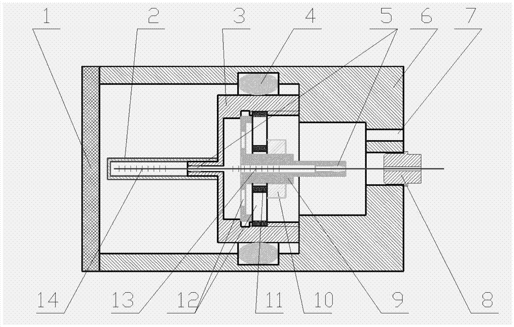
[0029] like figure 1 As shown, a fiber Bragg grating pressure sensor includes an outer protection tube 6 , a pressure measuring fiber Bragg grating 13 , a temperature measuring fiber Bragg grating 14 , a fixed pressure plate 11 , an elastic substrate 9 and an elastic diaphragm 3 . The elastic diaphragm 3 is arranged in the outer protection tube 6, and separates the outer protection tube 6 to form a measured fluid cavity and a reference fluid cavity, the measured fluid cavity communicates with the measured fluid, and the reference fluid cavity communicates with the atmosphere. The outer protection tube 6 is provided with a filter screen 1 on one side of the measured fluid chamber, and a plug 8 and an atmosphere communication hole 7 are provided on the side of the reference fluid chamber, so that the reference fluid chamber and the atmosphere are connected, effectively eliminating the residual gas pressure inside the sensor or The effect of changes in external atmospheric pressu...
Embodiment 2
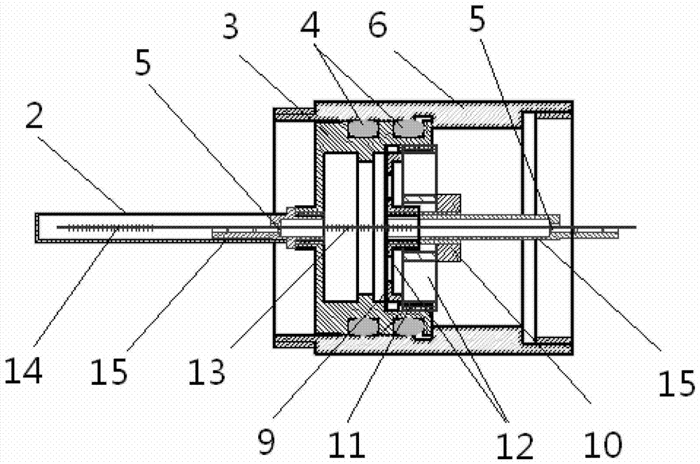
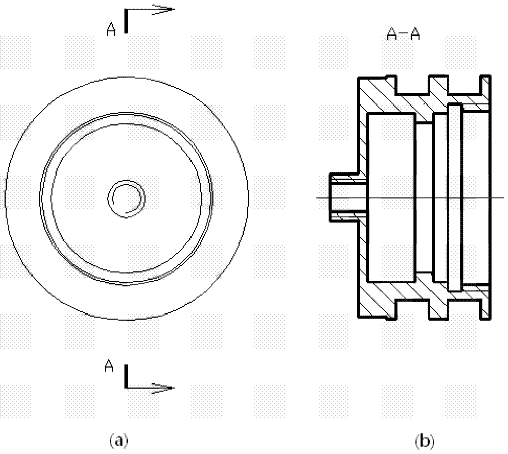
[0034] like Figure 2~4 As shown, there are two "O"-shaped sealing rings 4 of the fiber grating pressure sensor in this example, and the installation grooves are opened on the elastic diaphragm. Each of the elastic substrate 9 and the fixed platen 11 has a set of vent holes 12, wherein the number of vent holes 12 on the elastic substrate 9 is four, and the number of vent holes 12 on the fixed platen 11 is six. The welding point 5 of optical fiber can be located on a base 15, and this base 15 can directly be made into an integral body with elastic diaphragm 3, elastic substrate 9, also can be used as separate parts with elastic diaphragm 3, elastic substrate 9 connect.
PUM
Abstract
The invention relates to a fiber grating pressure sensor, which comprises an outer protection tube, a pressure measuring fiber grating, an elastic substrate and an elastic diaphragm. The elastic diaphragm is arranged in the outer protection tube and separates the outer protection tube to form a measured fluid cavity and a reference fluid cavity. , the measured fluid cavity is connected to the measured fluid, the reference fluid cavity is connected to the atmosphere, the elastic substrate is set in the reference fluid cavity, and is fixedly connected with the elastic diaphragm, and the pressure sensor also includes a temperature-measuring fiber grating, which is connected to the temperature-measuring fiber grating The pressure fiber grating is connected in series on the same optical fiber, the fiber passes through the elastic substrate and the elastic diaphragm, the pressure measurement fiber grating is located in the reference fluid cavity, and the two ends of the pressure measurement fiber grating are respectively fixed on the elastic substrate and the elastic diaphragm Above, the temperature measuring fiber grating is located in the measured fluid chamber, one end of the temperature measuring fiber grating is connected to the pressure measuring fiber grating, and the other end is a free end. Compared with the prior art, the present invention has the advantage of high measurement accuracy.
Description
technical field [0001] The invention relates to a pressure sensor, in particular to an optical fiber grating pressure sensor with a temperature measuring function. Background technique [0002] Fluid pressure sensor is a sensor with a wide range of uses, such as bridges, dams, hydrology, tunnels, chemical industry, meteorology, slopes, etc., commonly used sensing elements for detection or monitoring. Among the various existing detection schemes, due to temperature interference, electromagnetic interference, safety, long-distance transmission, service life, reliability and other reasons, it is impossible to solve the pressure detection problems of this series of industries well. [0003] The fiber grating pressure sensor can solve the problems caused by temperature interference, electromagnetic interference, safety, long-distance transmission, service life, reliability, etc. in the current detection scheme. However, the existing fiber grating pressure sensors generally do no...
Claims
Application Information
Patent Timeline
Application Date:The date an application was filed.
Publication Date:The date a patent or application was officially published.
First Publication Date:The earliest publication date of a patent with the same application number.
Issue Date:Publication date of the patent grant document.
PCT Entry Date:The Entry date of PCT National Phase.
Estimated Expiry Date:The statutory expiry date of a patent right according to the Patent Law, and it is the longest term of protection that the patent right can achieve without the termination of the patent right due to other reasons(Term extension factor has been taken into account ).
Invalid Date:Actual expiry date is based on effective date or publication date of legal transaction data of invalid patent.

