
Self-locking bearing groove with self-provided locking buckle of elastic ring on working wing

A technology of self-locking brackets and elastic rings, applied in the direction of brackets, arch wires, etc., can solve the problems of patient discomfort, fracture, cumbersome and inconvenient wire removal operations, etc.

Active Publication Date: 2012-11-14
江苏盛玛特新材料科技有限公司
View PDF5 Cites 7 Cited by
  • Summary
  • Abstract
  • Description
  • Claims
  • Application Information

AI Technical Summary

Problems solved by technology

In this patent, one or two sheet-shaped self-locking parts are arranged in the space between the tops of the two side walls of the groove, and the elastic deformation of the sheet-shaped self-locking parts in the range of the slot below it is used to realize the bracket Therefore, the range of motion of the sheet-shaped self-locking part is very limited, and there are problems such as difficulty in inserting large-sized arch wires (such as arch wires with a wire diameter of 0.021 inches × 0.025 inches) into the slots in clinical applications.
Moreover, due to the bending deformation of the sheet-shaped self-locking part relative to the side wall of the groove during the insertion of the archwire, the stress concentration at the connection part between the sheet-shaped self-locking part and the top of the side wall of the groove is concentrated, so the connection part is easier Permanent deformation or fracture occurs, that is, the connection part is easy to deform or break after repeated bending, so that the bracket loses its self-locking function and the control of the arch wire
In addition, in clinical practice, orthodontists often need to take out the arch wire that has been placed in the groove, readjust it, and then put it into the bracket groove. However, this patent does not consider how to remove the arch wire conveniently. As a result, the operation of taking wire is cumbersome and inconvenient, and requires a lot of force, which is likely to cause discomfort to the patient and deformation and fracture of the self-locking parts

Method used


Image

  • Self-locking bearing groove with self-provided locking buckle of elastic ring on working wing
  • Self-locking bearing groove with self-provided locking buckle of elastic ring on working wing
  • Self-locking bearing groove with self-provided locking buckle of elastic ring on working wing

Examples


Embodiment 1

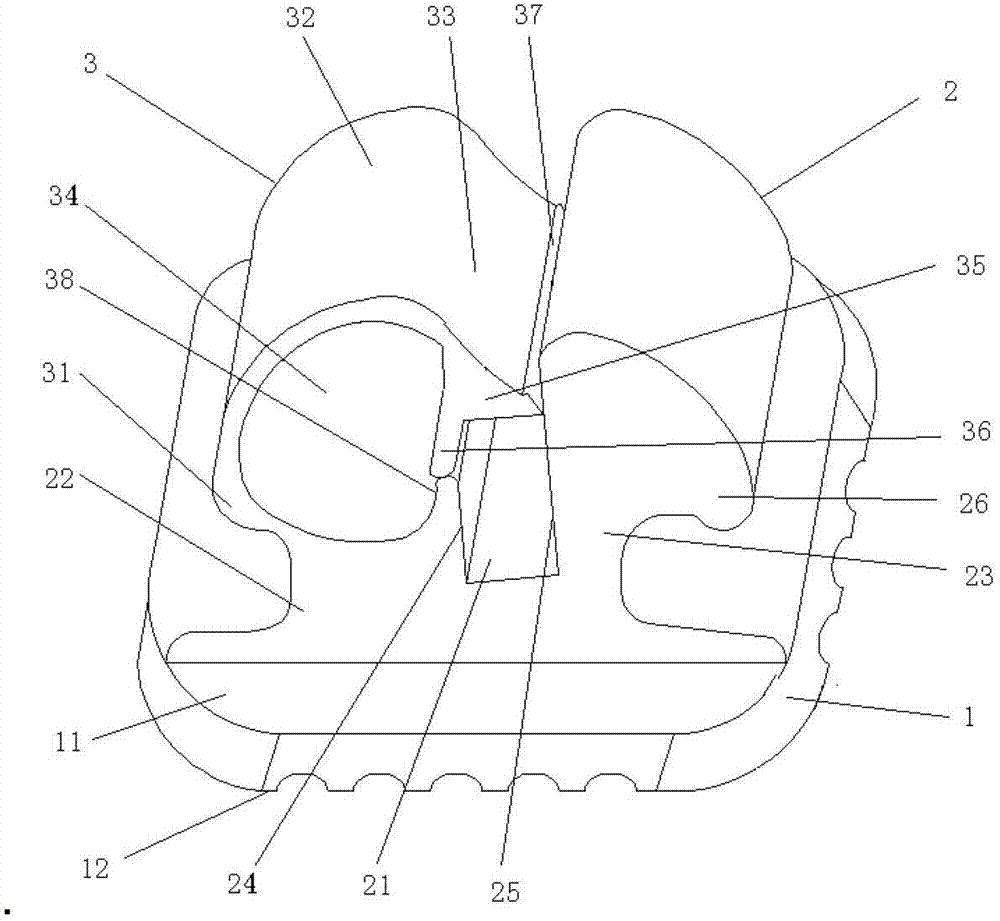
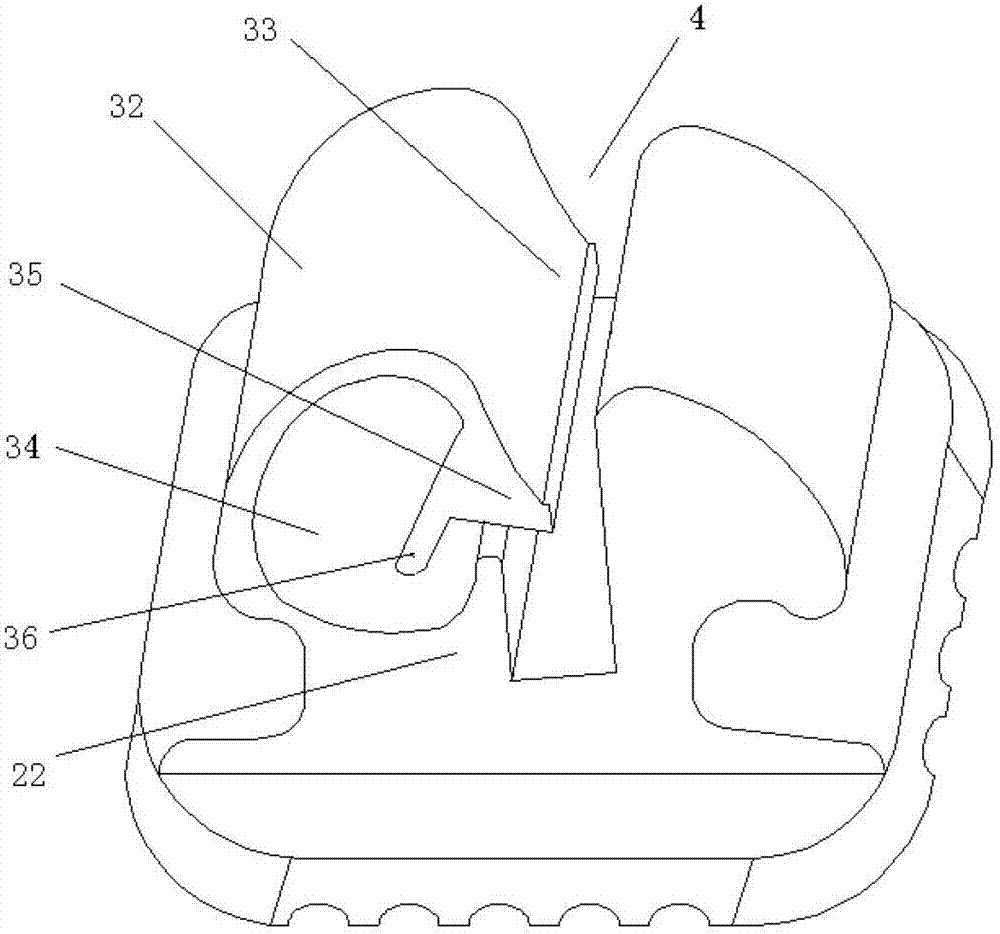
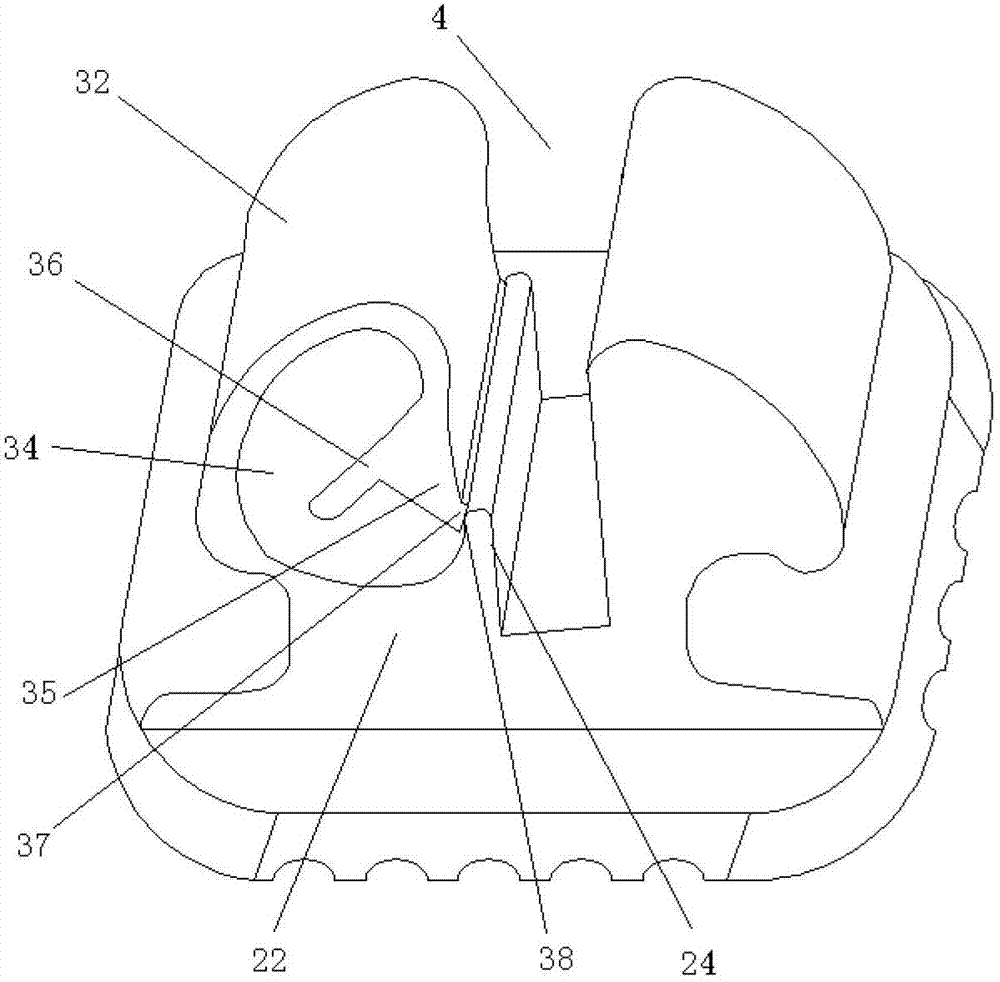
[0040] Such as figure 1 As shown, the self-locking bracket of this embodiment includes a bracket bottom plate 1 , working wings 2 and elastic ring lockers 3 , and each working wing 2 is provided with an elastic ring locker 3 . Among them, the front of the bracket bottom plate 1 is the lip and buccal surface 11, and the back is the adhesive surface 12. The lip and buccal surface 11 is a smooth plane, and the adhesive surface 12 is provided with a gully-like texture, which is conducive to the inflow of adhesive and strengthens the self-locking bracket. Adhesive retention. The working wing 2 includes a base connected to the surface 11, and a groove 21 formed by the top of the base recessed downward for installing an orthodontic archwire. The grooves 21 of all the working wings 2 are on a groove axis. The base is divided into the first base 22 on one side of the groove axis and the second base 23 on the other side of the groove axis by the groove 21, the groove wall on the first ...

Embodiment 2

[0046] Such as Figure 5 As shown, the difference between this embodiment and Embodiment 1 is that a piece 39 protrudes from the end of the free end 33 toward the inner side of the elastic piece 32 . Such as Figure 6 , Figure 7 As shown, when the elastic piece 32 is deformed, the end of the supporting piece 39 is closer to the inner surface of the elastic piece, until the deformation of the elastic piece 32 reaches a certain degree, the end of the supporting piece 39 is against the inner surface of the elastic piece 32, limiting the continued deformation of the elastic piece 32 . Such as Figure 8 As shown, when the free end 33 is subjected to an external force and the shrapnel 32 is deformed, the card 35, the blocking piece 36, and the support piece 39 move synchronously, so that the entrance 4 of the archwire groove is formed, the archwire is restricted in the archwire groove and the shrapnel is restricted. 32 The function of excessive deformation is completed in one s...


PUM

PropertyMeasurementUnit
Thicknessaaaaaaaaaa

Abstract

The invention relates to a self-locking bearing groove with a self-provided locking buckle of an elastic ring on a working wing, which comprises a bottom plate of the bearing groove and a working wing arranged at the buccal labial face of the bottom plate of the bearing groove, wherein the working wing comprises a base connected with the bottom plate of the bearing groove, the middle part of the base is downwards recessed so as to form slots, and all the slots are arranged on the axis of one slot; the base is divided into a first base and a second base by the axis of the slot; the self-locking bearing groove with the self-provided locking buckle of the elastic ring on the working wing is characterized in that: the top of the first base is provided with a locking buckle of an elastic ring, the locking buckle of the elastic ring comprises a spring piece and a free end, one end of the spring piece is fixed with the first base, the other end is connected with the free end, the spring piece is a bending piece with elasticity, and the free end is suspended above the buccal labial face of the working wing; a clamping piece and a blocking piece which extend out towards different directions are arranged on the free end; and when the spring piece is at a loose state, the clamping piece, the blocking piece and the slots form an arch wire groove together. The clamping piece and the blocking piece are simultaneously and synchronously moved, so that the functions of closing an outlet / inlet port of an arch wire and restricting the arch wire in the arch wire groove are simultaneously realized.

Description

technical field [0001] The invention relates to the field of dental orthodontic instruments, in particular to a self-locking bracket with an elastic ring lock on the working wing. Background technique [0002] Orthodontic treatment is a highly specialized branch of dentistry, mainly for the correction of teeth, jaws, and facial deformities, and gradually restores the normal occlusal function of patients by fixing orthodontic appliances inside the oral cavity. Brackets are an important part of orthodontic appliances. They are mainly bonded to front teeth, canines, and premolars. Orthodontic treatment guides the misaligned teeth to move to the ideal position by installing the orthodontic arch wire in the groove of the bracket. s position. [0003] The traditional brackets are fixed in the groove by ligating wires or elastic rubber rings, but this fixing method has the disadvantages of time-consuming and inconvenient clinical operation, high friction, and poor comfort. In rec...

Claims


Application Information

Patent Timeline
IPC IPC(8): A61C7/14
CPCA61C7/30A61C7/285
Inventor 黄兵民
Owner 江苏盛玛特新材料科技有限公司
Learn More