Supercharge Your Innovation With Domain-Expert AI Agents!

screwdriver with torque limiter

A torque limiter, torque limiting technology, applied to screwdrivers, manufacturing tools, wrenches, etc., can solve problems such as torque limiting mechanism wear

Active Publication Date: 2016-03-16
WIHA WERKZEUGE
View PDF8 Cites 0 Cited by
  • Summary
  • Abstract
  • Description
  • Claims
  • Application Information

AI Technical Summary

Problems solved by technology

Here, the torque limiting mechanism suffers from wear

Method used


Image

  • screwdriver with torque limiter
  • screwdriver with torque limiter
  • screwdriver with torque limiter

Examples


Embodiment Construction

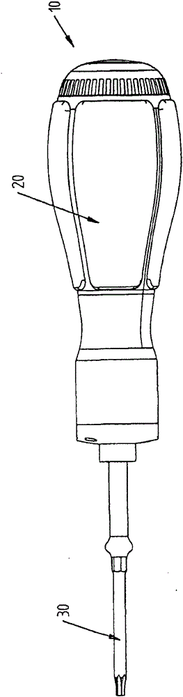
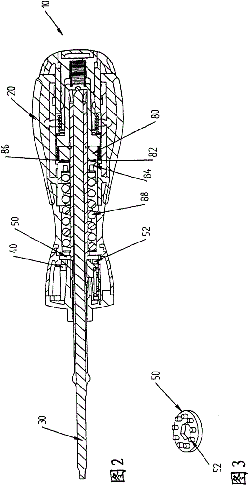
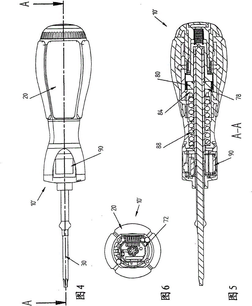
[0027] Figures 1 to 3 A first exemplary embodiment of a screwdriver 10 is shown with a handle 20 into which a torque limiting mechanism is integrated and into which a rod 30 is inserted coaxially. The torque limiting mechanism is not the subject of the invention and can be constructed in different embodiments. Importantly, the rod 30 is coaxially rotatably inserted into the handle 20 and the torque applied to the handle 20 is transmitted to the rod 30 through a coupling 78 of the torque limiting mechanism. In this case, the coupling 78 is acted upon, for example, by a compression spring 88 designed as a helical spring, which holds the coupling 78 engaged with axial pressure. The coupling 78 has a first coupling element 80 and a second coupling element 84 . In this case, the first coupling element 80 is connected in a rotationally fixed manner to the lever 30 , while the second coupling element 84 is connected in a rotationally fixed manner to the handle 20 . In this case, ...


PUM


Abstract

The screw driver (10) has a torque limiting handle (20) and a shank (30) which is coaxially inserted opposite the handle that is rotatably coupled and is torsionally connected through the torque limiter. The relative rotation between the shaft and the handle represents the switching cycle by the defined angle. A counting unit is provided for counting the cycles. A Hall sensor (40) is rotatably connected to the handle and the magnetic element (52) is rotationally fixed to the shaft.

Description

technical field [0001] The invention relates to a screwdriver with a torque limiter. Background technique [0002] Screwdrivers with a handle comprising a torque limiter and a shaft inserted coaxially into the handle are known, the shaft being rotatable relative to the handle and torque-locked (drehmomentschlüssig) with the handle via the torque limiter A coupling wherein each relative rotation between the lever and the handle by at least one defined angle represents a switching cycle. A screwdriver with a torque limiter is advantageous in order to be able to tighten the screw with a predetermined force which, on the one hand, guarantees a secure hold of the screw connection and, on the other hand, excludes overstressing of the thread. Thus, the lever can be turned within the handle in order to be able to disengage the torque limiting mechanism. When the torque transmitted from the handle to the rod through the coupling exceeds the limit torque, the torque limiting mechani...

Claims


Application Information

Patent Timeline
Patent Type & Authority Patents(China)
IPC IPC(8): B25B23/142B25B15/02
CPCB25B23/1422B25B15/02
Inventor O·卡勒
Owner WIHA WERKZEUGE
Features
  • R&D
  • Intellectual Property
  • Life Sciences
  • Materials
  • Tech Scout
  • Unparalleled Data Quality
  • Higher Quality Content
  • 60% Fewer Hallucinations
Learn More