Self-elevating type platform buoyant pile shoe with function of reducing resistance in pile pulling

A self-elevating platform and buoyancy technology, which is applied to sheet pile walls, water conservancy projects, artificial islands, etc., can solve the problems of not pulling out piles, too deep into the mud of platform pile legs, and difficulty in pulling out piles when the platform is evacuated, so as to avoid The effect of sea mud entering and reducing the degree of soil compaction

Inactive Publication Date: 2012-11-14
CHINA UNIV OF PETROLEUM (BEIJING)
View PDF6 Cites 4 Cited by
  • Summary
  • Abstract
  • Description
  • Claims
  • Application Information

AI Technical Summary

Problems solved by technology

However, on the soft seabed, the pile legs of the platform often go too deep into the mud after preloading, sometimes even exceeding 30 meters, which makes it very difficult for the platform to evacuate and pull out the piles after the drilling operation is completed.
The existing method is to scour the bottom of the pile and the surrounding area to eliminate the adsorption force of the shoe bottom and reduce the strength of the soil at the bottom, so as to reduce the pile pulling resistance. However, when the pile leg is too deep into the mud, the weight of the deposited soil and the corresponding The consolidation will add great resistance to pile pulling, and eventually the platform will not be able to pull piles for a long time, and even need to use dredgers to dig piles. drilling operation

Method used


Image

  • Self-elevating type platform buoyant pile shoe with function of reducing resistance in pile pulling
  • Self-elevating type platform buoyant pile shoe with function of reducing resistance in pile pulling
  • Self-elevating type platform buoyant pile shoe with function of reducing resistance in pile pulling

Examples


Embodiment Construction

[0014] The present invention will be described in detail below in conjunction with the accompanying drawings.

[0015] The implementation method of the present invention can be summarized as the following contents:

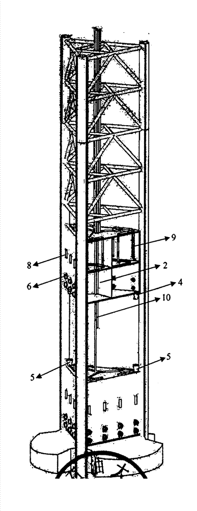
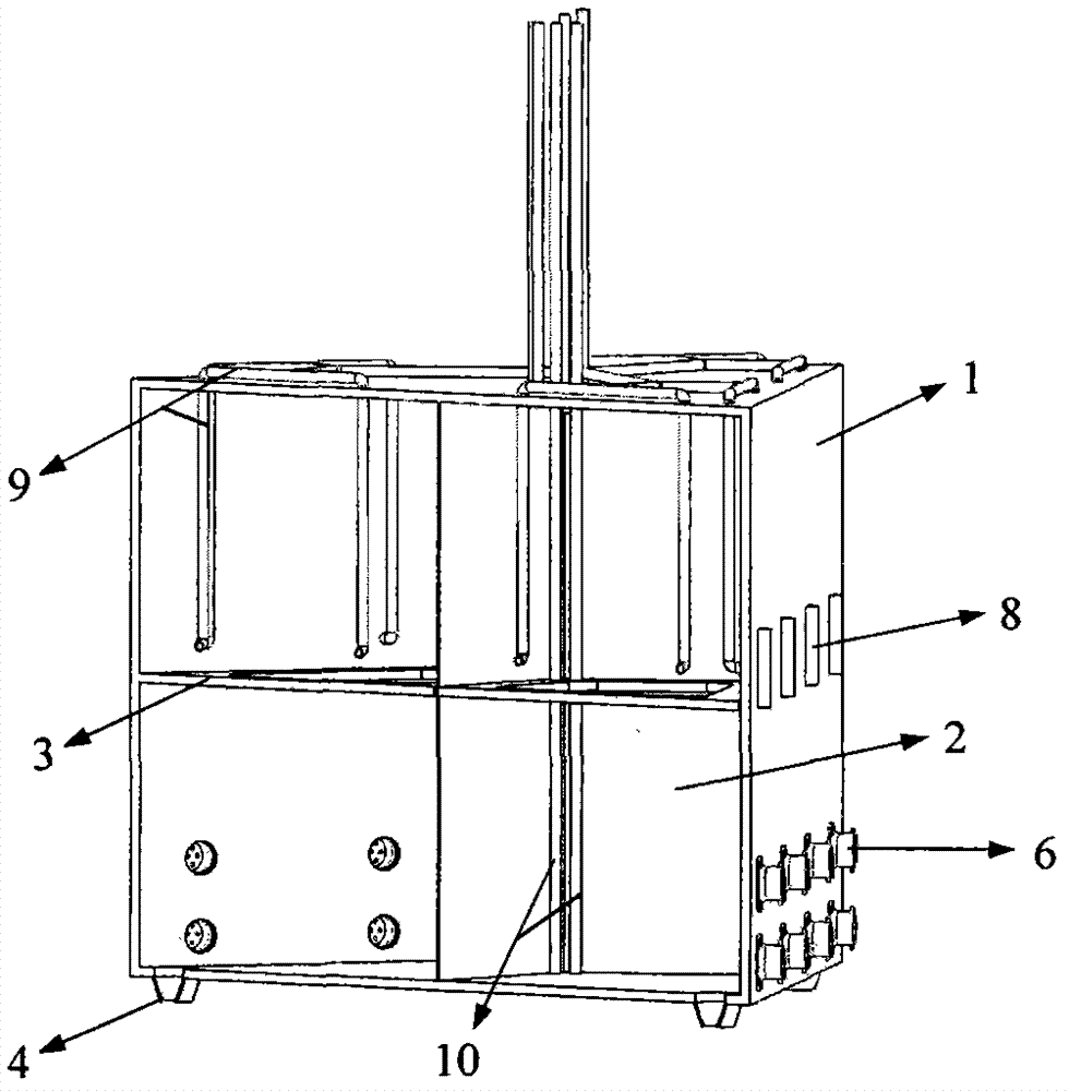
[0016] 1) The buoyancy spud boots are equipped with three sets of buoyancy tanks 1, and each buoyancy tank is equipped with three prismatic ballast tanks 2 and reinforcement rings 3. The pier 4 and the bell mouth 5 are limited and welded. The outside of the pontoon is still the three main columns of the pile legs, and the racks on the columns are connected, so the pontoon does not affect the lifting pile operation of the platform. See figure 1 .

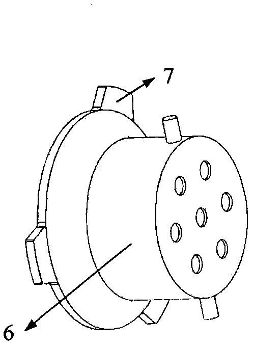
[0017] 2) The lower part of the buoyancy tank is provided with a permeable water-passing device 6, which contains compacted steel wire balls and is installed on the outside of the buoyancy tank through buckles 7, see figure 2 . Steel wire clusters with different degrees of compaction can be selected to adjust the p...


PUM


Abstract

The invention relates to a self-elevating type platform buoyant pile shoe with a function of reducing the resistance in pile pulling. The self-elevating type platform buoyant pile shoe is characterized by comprising floating boxes, permeable water passing devices, washing holes, washing pipelines and gas injection pipelines, wherein the upper part of the pile shoe is provided with three floating boxes; each floating box consists of three prismatic ballast tanks; the gas injection pipelines in the tanks can inject air into the three ballast tanks for discharging ballast water; and the lower parts of the outer sides of the floating boxes are provided with the permeable water passing devices which are taken as water discharging channels and can block sea mud from entering. The washing holes are arranged under mud covers at the outer sides of the floating boxes and are used for washing periodically and preventing soil bodies near a pile leg from being solidified. The buoyant pile shoe has the advantages that the space of a pile pit is occupied by means of the floating boxes, the backfill amount of marine-soil silts during the operation of a platform is reduced, and the pile pulling resistance caused by the weight of silted soil is greatly reduced; and simultaneously, certain buoyancy can be provided by discharging of the ballast water in pile pulling, and the pile lifting load of a lifting mechanism is relieved, so that smooth pile pulling is realized.

Description

technical field [0001] The invention relates to a self-elevating platform buoyancy spud shoe with the function of pulling out piles and reducing resistance. Background technique [0002] Jack-up platforms generally obtain a strong enough sea-soil foundation on the seabed by preloading. After releasing the ballast water, the compacted soil at the bottom of the pile provides support for subsequent drilling operations. However, on the soft seabed, the platform pile legs often enter the mud too deep after preloading, sometimes even exceeding 30 meters, which brings great difficulties to the platform evacuation and pile extraction after the drilling operation is completed. The existing method is to scour the bottom of the pile and the surrounding area to eliminate the adsorption force of the shoe bottom and reduce the strength of the soil at the bottom, so as to reduce the pile pulling resistance. However, when the pile leg enters the mud too deep, the weight of the deposited soi...

Claims


Application Information

Patent Timeline
Patent Type & Authority Applications(China)
IPC IPC(8): E02D5/72E02B17/00
Inventor 赵天奉段梦兰
Owner CHINA UNIV OF PETROLEUM (BEIJING)
Why Eureka
Try Eureka