High-volume utilization rate fuel tank

A technology with high utilization rate and high volume, which is applied in the direction of liquid fuel feeder, engine components, machines/engines, etc. It can solve the problem of not being able to absorb oil, reduce inventory, facilitate installation and maintenance, and improve actual utilization. Effect

Active Publication Date: 2012-11-14
GUANGXI LIUGONG MASCH CO LTD
View PDF7 Cites 9 Cited by
  • Summary
  • Abstract
  • Description
  • Claims
  • Application Information

AI Technical Summary

Problems solved by technology

[0004] The object of the present invention is to provide a fuel tank that can still take oil when the fuel tank is small and the fuel tank is tilted, aiming at the shortcomings of the existing fuel tank that the oil pipe cannot absorb oil when the fuel tank is small and the fuel tank is tilted. High volume utilization fuel tank with high actual utilization rate of fuel and fuel tank volume

Method used


Image

  • High-volume utilization rate fuel tank
  • High-volume utilization rate fuel tank
  • High-volume utilization rate fuel tank

Examples


Embodiment Construction

[0030] The specific implementation will be described below in conjunction with the accompanying drawings.

[0031] Figure 3 to Figure 13 A preferred implementation of the present invention is shown, and the implementation of this example can be applied to other construction machinery equipment.

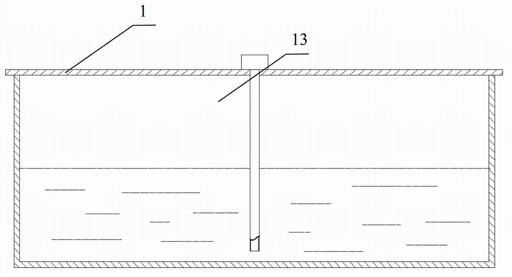
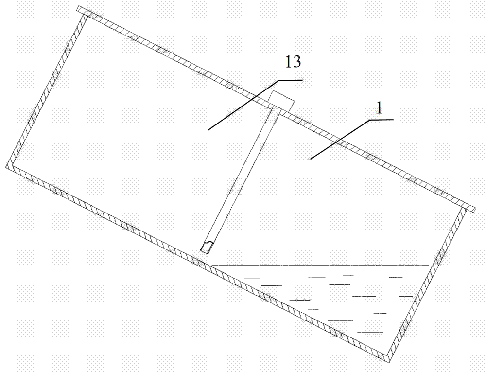
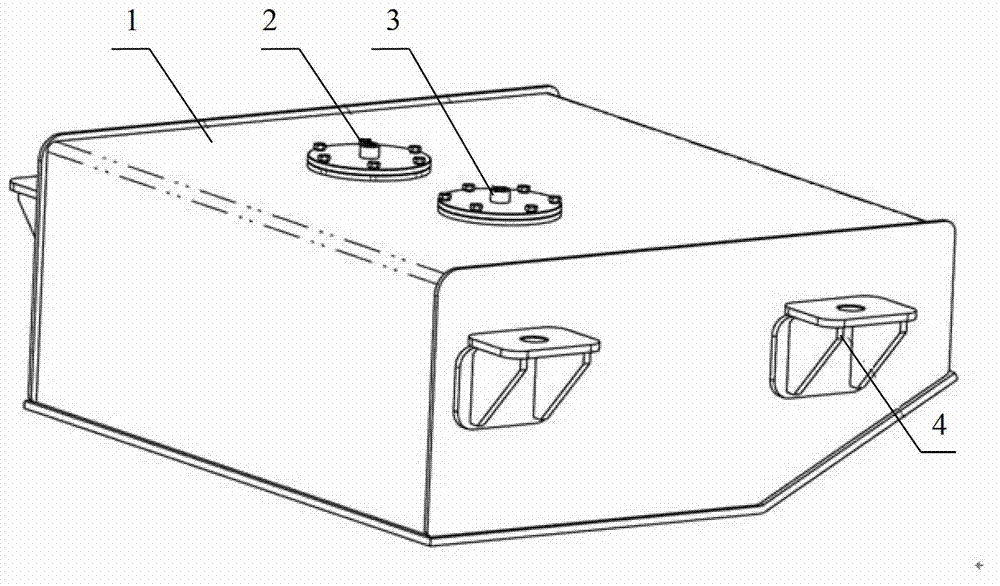
[0032] Such as image 3 , Figure 4 Shown is a rear-mounted diesel tank for a wheel loader. The diesel tank is composed of a tank body 1, an oil suction device 2, an oil return device 3 and a mounting support 4 for the fuel tank. The tank body 1 is an approximately square structure, and its bottom plate is the rear The bending plate is bent upwards at the top, and the bending angle is determined according to the requirements of the departure angle of the whole machine to ensure that the diesel tank is within the envelope of the departure angle of the whole machine. Such as Figure 5 As shown, the oil suction device 2 is composed of an oil suction flange 5, an oil suction joint 12...


PUM


Abstract

The invention relates to a high-volume utilization rate fuel tank which solves the defect that fuel is not sucked by a fuel sucking pipe when the traditional fuel tank has little fuel and inclines. The fuel tank comprises a tank body, wherein a fuel sucking device is arranged in the tank body and comprises a fuel sucking joint, a fuel sucking soft tube and a fuel sucking nozzle, wherein one end of the fuel sucking soft tube is fixed on the middle-upper part of the tank body through the fuel sucking joint, the other end of the fuel sucking soft tube is connected with the fuel sucking nozzle, the fuel sucking nozzle is arranged on the bottom of the tank body, and the fuel sucking nozzle can slide to a low position from a high position of the tank body under the action of the gravity. When the fuel tank has little fuel and inclines, the fuel sucking nozzle can move to a fuel accumulation area at the low place of the fuel tank so that fuel can be sucked without causing stalling of an engine, therefore, the requirement on the minimum fuel quantity in the fuel tank can be reduced, and the actual utilization rate of the volume of the fuel tank is increased.

Description

[0001] technical field [0002] The invention relates to a fuel tank, in particular to a fuel tank with high volume utilization rate used on construction machinery equipment. technical background [0003] Most construction machinery and equipment are driven by internal combustion engines, so such machinery and equipment are equipped with fuel tanks for storing fuel, and oil is taken from the fuel tank through the oil suction pipe to supply fuel to the engine. In the existing fuel tank, the oil-taking end of the oil-absorbing hard pipe 13 is all fixed on a certain position at the bottom of the fuel tank casing 1, such as figure 1 As shown, this kind of fuel tank will not have the problem that the oil suction pipe cannot get oil when the fuel is sufficient, but when there is less fuel in the fuel tank and the machinery and equipment are located on the slope, the fuel tank body 1 will follow along with it. Tilt forward and backward with the machine equipment, such as figu...

Claims


Application Information

Patent Timeline
Patent Type & Authority Applications(China)
IPC IPC(8): F02M37/02
Inventor 张碧荣王涛刘阳江彭拔萃廖玉懂孙峰谭艳
Owner GUANGXI LIUGONG MASCH CO LTD
Why Eureka
Try Eureka