

Bill depositing and dispensing device
A banknote and cashier technology, which is applied to the device for accepting coins, handling coins or valuable banknotes, instruments, etc., can solve the problems of longer lead wire length, higher device price, and more cable guide parts, etc., to achieve the realization price , structure simplification, and the effect of shortening the banknote conveying path
- Summary
- Abstract
- Description
- Claims
- Application Information
AI Technical Summary
Problems solved by technology
Method used
Image

Examples
no. 1 Embodiment approach
[0042] [Structure of banknote depositing and dispensing device]
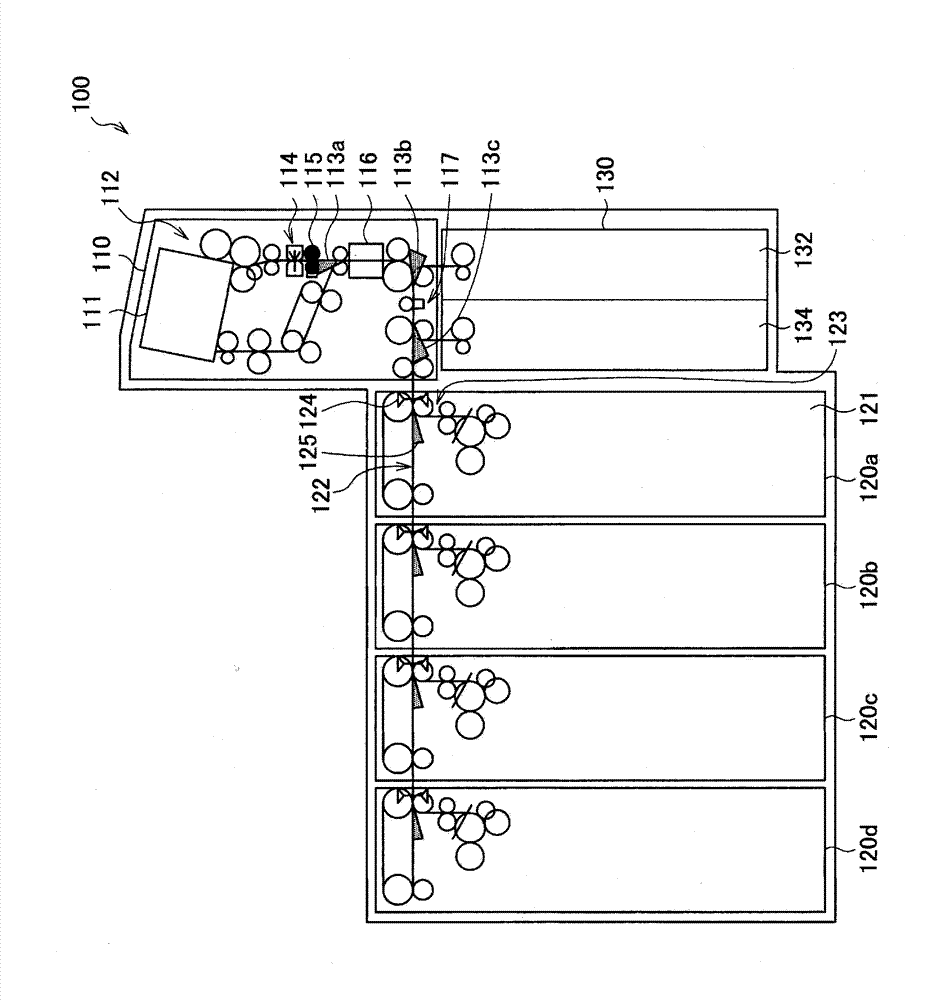
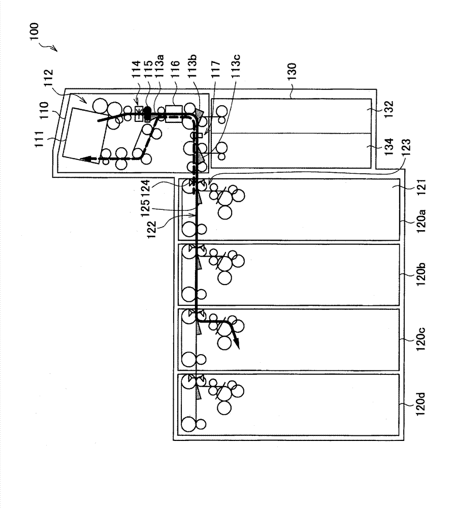
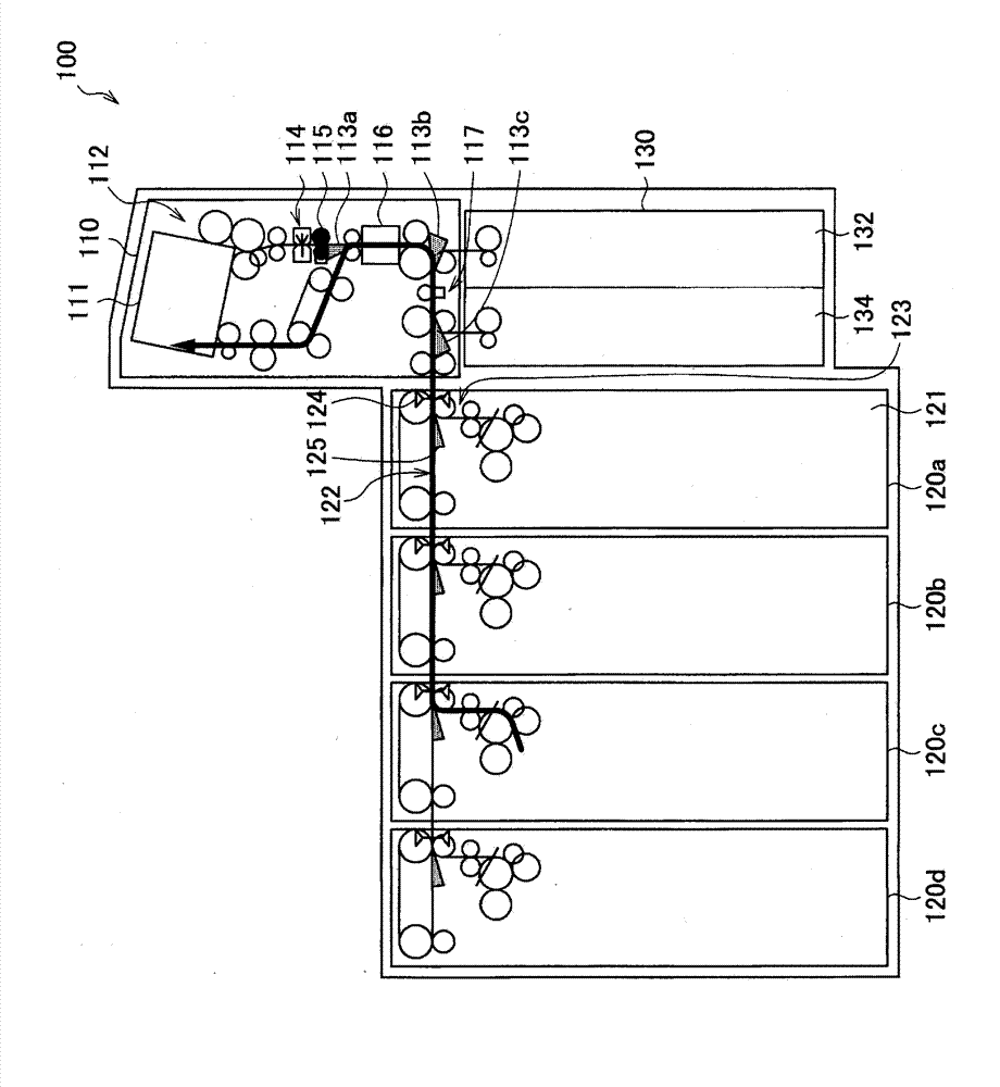
[0043] First, refer to figure 1 The schematic structure of the banknote depositing and dispensing apparatus of 1st Embodiment of this invention is demonstrated. figure 1 It is a schematic structural diagram which shows the structure of the banknote depositing and dispensing apparatus 100 of this embodiment.
[0044] Such as figure 1 As shown, the banknote depositing and dispensing device 100 of this embodiment is composed of a reception unit 110 , storage boxes 120 ( 120 a - 120 d ), and a returning / taking unit 130 .
[0045] The reception unit 110 is a unit for handing over banknotes to a user. Such as figure 1 As shown, the reception unit 110 has a reception opening 111, and the reception opening 111 has a delivery mechanism for sending out gold banknotes and an accumulation mechanism for accumulating gold banknotes. 120. The return / retrieval unit 130 is connected. On the path of the conveyance path ...
no. 2 Embodiment approach
[0073] [Structure of banknote depositing and dispensing device]
[0074] Next, refer to Figure 6 , the schematic structure of the banknote depositing and dispensing device according to the second embodiment of the present invention will be described. Figure 6 It is a schematic structural diagram which shows the structure of the banknote depositing and dispensing apparatus 200 of this embodiment. Compared with the banknote depositing and dispensing device 100 of the first embodiment, the banknote depositing and dispensing device 200 of this embodiment is different in that the thickness sensors 124 provided in the storage boxes 120 a - 120 d are integrated into one and provided in the reception unit 210 . Hereinafter, the same structure and function as the banknote depositing and dispensing device 100 of the first embodiment will be briefly described, and the points of difference from the banknote depositing and dispensing device 100 of the first embodiment will be mainly des...
no. 3 Embodiment approach
[0086] [Structure of banknote depositing and dispensing device]
[0087] Next, refer to Figure 7 and Figure 8 The schematic structure of the banknote depositing and dispensing apparatus of 3rd Embodiment of this invention is demonstrated. Figure 7 It is a schematic structural diagram showing the structure of the banknote depositing and dispensing apparatus 300 of this embodiment. Figure 8 It is explanatory drawing which shows the motor drive range of the banknote depositing and dispensing apparatus 300 of this embodiment. The difference between the banknote depositing and dispensing device 300 of the present embodiment and the banknote depositing and dispensing device 100 of the first embodiment is that the banknote depositing and dispensing device 300 of the present embodiment uses the first transport path 122 provided in each storage cassette 120a-120d, the thickness sensor 124 and the switching mechanism 125 are assembled in a unit different from the storage box 120 ...
PUM
 Abstract
Description
Claims
Application Information