Method for setting double-row road surface speed control edge lines for controlling vehicle speed

An edge line and vehicle speed technology, applied in the field of traffic safety, can solve problems such as underestimation of vehicle speed, and achieve the effect of increasing perceived speed, improving driving safety, and reducing subjective acceleration awareness.

Inactive Publication Date: 2012-11-21
WUHAN UNIV OF TECH
View PDF5 Cites 8 Cited by
  • Summary
  • Abstract
  • Description
  • Claims
  • Application Information

AI Technical Summary

Problems solved by technology

Theoretically, the greater the edge rate, the greater the driver's speed perception. However, due to the limit of the driver's visual system's ability to distinguish time, generally after the edge rate and optical flow rate reach 20-55Hz, the flash fusion phenomenon will occur, that is, street flash fusion. The appearance of the frequency makes the subjects underestimate the speed of the vehicle

Method used


Image

  • Method for setting double-row road surface speed control edge lines for controlling vehicle speed
  • Method for setting double-row road surface speed control edge lines for controlling vehicle speed
  • Method for setting double-row road surface speed control edge lines for controlling vehicle speed

Examples


Embodiment Construction

[0022] Working principle of the present invention is:

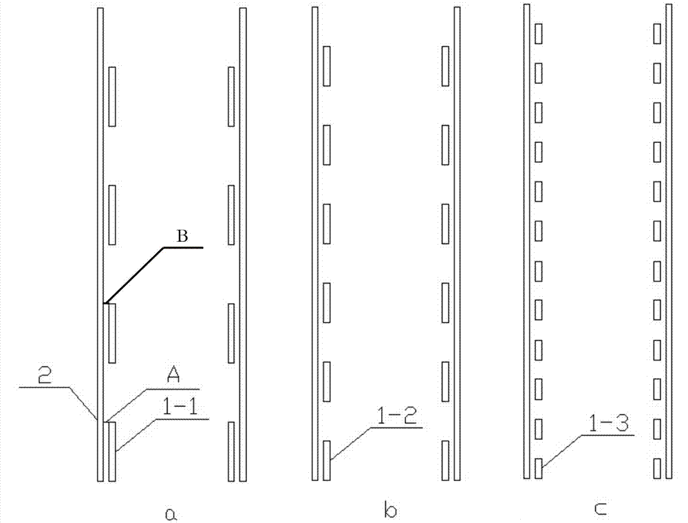
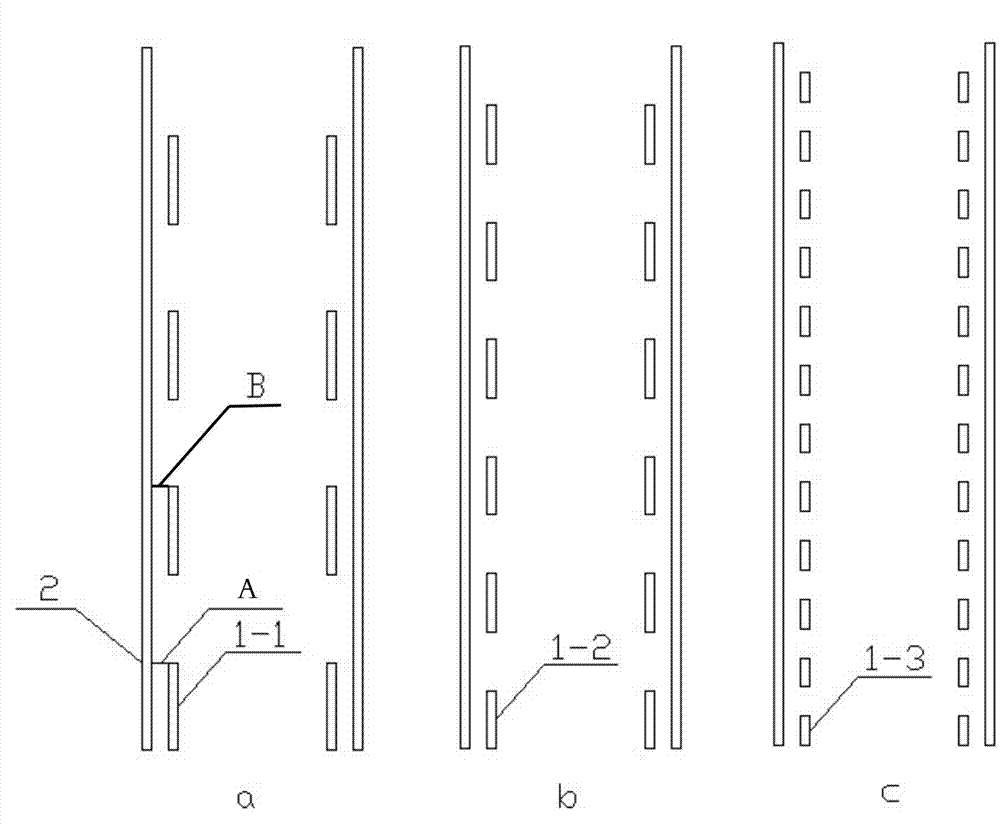
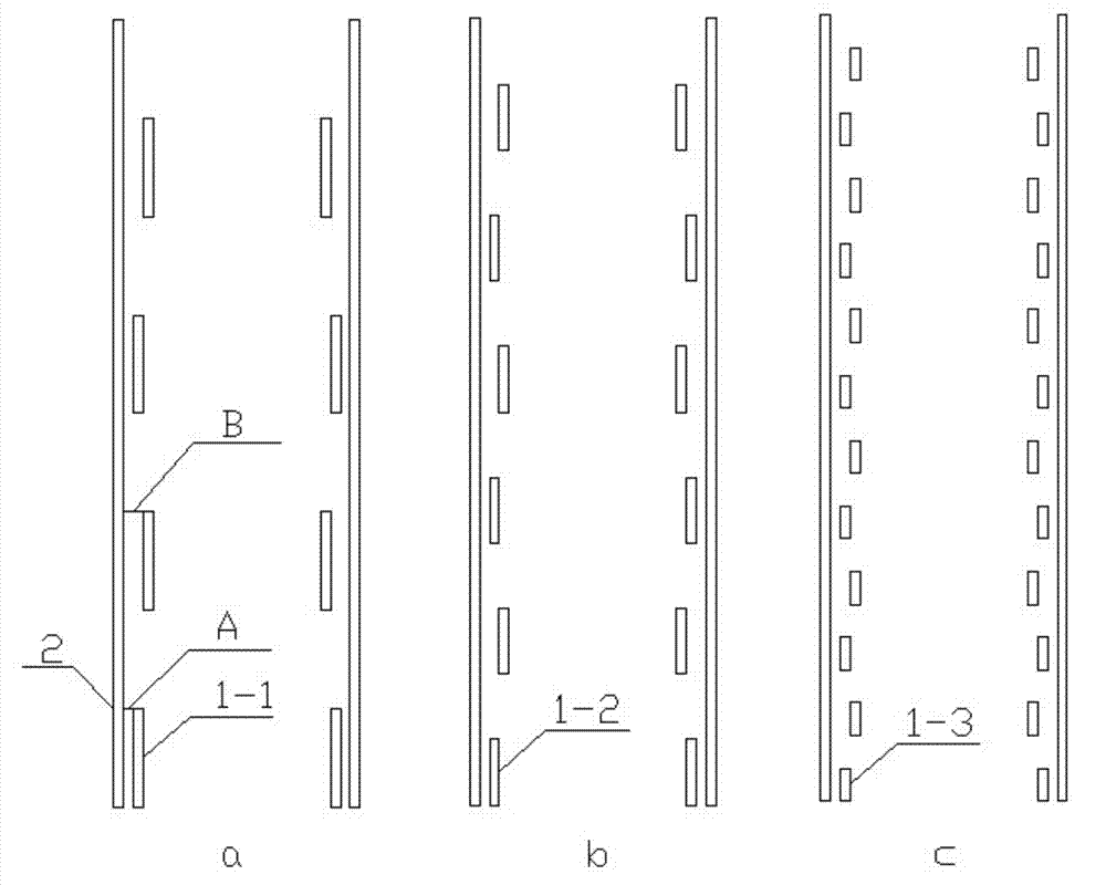
[0023] (1) Based on the edge rate and optical flow rate of the driver's visual perception (referring to changing the edge rate and optical flow rate of the driver's visual perception by artificially changing the road markings on the expressway) before entering the local dangerous section of the expressway Pave the speed control edge line on the road surface to increase the driver's perceived speed, improve the driver's subjective awareness of danger, improve the driver's subjective awareness of seeking safety, reduce the driver's subjective acceleration awareness, and enable the driver to subjectively control driving. Speed, so as to achieve the purpose of speed limit;

[0024] (2) On the basis of the above-mentioned speed control edge line design of the road surface, a hot-melt fast-drying color road surface anti-skid paint is used, and the color is selected as yellow. The lane can be maintained when the lane is narrowe...


PUM

PropertyMeasurementUnit
lengthaaaaaaaaaa

Abstract

The invention provides a method for setting double-row road surface speed control edge lines for controlling the vehicle speed. The method comprises the following steps that 1) the inner side of a lane cutting line is provided with speed control edge wires, and materials adopt hot melt type quick dry yellow pavement anti-slip paint, wherein ingredients in the paint has the weight ratio that hot melting kettles: granular calcium carbonate: calcium carbonate ultrafine micropowder: water-based paint quick dry agents is 300:10:5:6, and the hot melting kettle comprises the following ingredients in percentage by weight: 45 percent of acrylic resin, 20 percent of aggregate, 10 percent of plasticizers, 15 percent of pigment and 10 percent of fillings; and 2) the control speed edge lines are alternate by one dotted line and one full line and are in arrangement parallel to the lane cutting line, the length of the single speed control edge line is 0.4 to 2m, and the distance between the adjacent speed control edge lines is equal to the length of the speed control edge line. Through the arrangement of speed control edge lines, the optical flow rate and the edge rate of the visual perception of a driver are changed, the perception speed of the driver is accelerated, and the subjective acceleration consciousness is reduced, so the goal of speed limitation is reached.

Description

technical field [0001] The invention belongs to the technical field of traffic safety, and in particular relates to a method for setting a double-row road surface speed control edge line to control the speed of a vehicle starting from the driver's speed perception. Background technique [0002] Domestic statistical results on the causes of road traffic accidents are: 80%-85% of road traffic accidents are caused by drivers, 5%-10% of road traffic accidents are caused by road factors, and only 10% of road traffic accidents are caused by drivers. Even lower road traffic accidents are caused by vehicle factors. While the driver is driving, 80%-90% of the information is obtained by vision. [0003] At present, the optical flow rate and edge rate among the visual factors that affect the driver's speed perception have received extensive attention, and scholars at home and abroad have done some related research on this. Among them: Denton's (1980) application of deceleration at ro...

Claims


Application Information

Patent Timeline
Patent Type & Authority Applications(China)
IPC IPC(8): E01F9/08C04B26/04
Inventor 朱顺应刘兵王红张子培
Owner WUHAN UNIV OF TECH
Why Eureka
Try Eureka