Low-flow fast movable cylinder

A fast-moving, low-flow technology, applied in the direction of fluid pressure actuators, etc., can solve the problems of high configuration cost, complicated pipeline, and complex structure of two-speed cylinder, and achieve the effect of simple structure

Inactive Publication Date: 2012-11-21
EXPLORATION TECH RES INST OF CHINESE ACADEMY OF GEOLOGICAL SCI +1
View PDF10 Cites 12 Cited by
  • Summary
  • Abstract
  • Description
  • Claims
  • Application Information

AI Technical Summary

Problems solved by technology

[0002] Commonly used oil cylinders have the following problems: On the one hand, when the bore of the oil cylinder is large, a large flow rate is required to move the cylinder quickly, so a pump with a large flow rate is required to supply oil, which will lead to high configuration costs and complicated pipelines , and it is necessary to increase the switching circuit; on the other hand, when the rated displacement is constant, the oil cylinder cannot switch between various moving speeds by changing the oil circuit
[0003] For example, the publication date is September 14, 2011, and the Chinese invention patent application with the publication number CN102182720A discloses a two-speed oil cylinder, although the two-speed oil cylinder realizes the thrust through the pressure areas of different sizes of the moving piston rod and the large piston. The change can make the push speed and retraction speed of the oil cylinder faster when using a smaller pressure receiving area, but the structure of the two-speed oil cylinder is more complicated and not easy to process, and according to the setting structure of its oil circuit, the One end of the two-speed oil cylinder is connected to the oil tank. The main function of the oil tank is the oil return storage container of the working chamber. The pressure bearing capacity is less than 1MPA, so the oil circuit connected to the oil tank can only bear the working pressure less than 1MPA.
In addition, the design of the oil port channel of this two-speed oil cylinder cannot realize the mutual conversion between the constant speed and differential speed oil cylinders and the problem of flow matching in the constant speed and differential speed oil cylinders in the hydraulic system

Method used


Image

  • Low-flow fast movable cylinder
  • Low-flow fast movable cylinder

Examples


Embodiment Construction

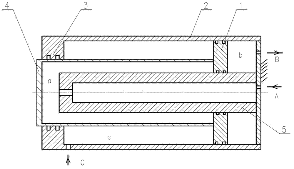
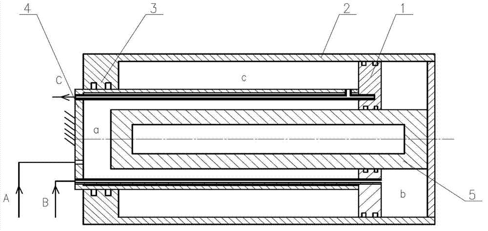
[0017] Such as figure 1 As shown, the small-flow fast-moving oil cylinder of the present invention includes a cylinder barrel 2, a piston 1, a hollow piston rod 4, and a hollow plunger 5; The inner cavity of the cylinder is divided into a first oil storage chamber c and a second oil storage chamber b. Those skilled in the art should know that the volumes of the first and second oil storage chambers will change with the relative movement between the piston and the cylinder One end of the piston rod 4 is fixedly connected to the side of the piston 1 forming the first oil storage chamber c, and the other end is used as an output end to connect with the side wall of the first oil storage chamber c opposite to the piston 1 in a closed sliding fit; the plunger One end of 5 is fixedly connected with the side wall of the second oil storage chamber b opposite to the piston 1, and the other end is connected with the piston in an airtight sliding fit, and extends into the hollow cavity o...


PUM


Abstract

The invention discloses a low-flow fast movable cylinder which comprises a cylinder barrel, a piston, a piston rod and a plunger. Both the piston rod and the plunger are hollow, an inner cavity of the cylinder barrel is divided into a first oil storage cavity and a second oil storage cavity by the piston, one end of the piston rod is fixedly connected with a side surface of the piston, and the other end of the piston rod is connected with a side wall of the first oil storage cavity in a sliding fit manner; one end of the plunger is fixedly connected with a side wall of the second oil storage cavity, the other end of the plunger is connected with the piston in a sliding fit manner and extends into a hollow cavity of the piston rod, an opening is arranged on the plunger, a hollow cavity of the plunger is communicated with the hollow cavity of the piston rod via the opening, so that a third oil cavity is formed between the piston rod and the plunger; and a third oil port, a second oil port and a first oil port which are respectively communicated with the hollow cavity of the plunger, the second oil storage cavity and the first oil storage cavity are arranged on the wall of the cylinder barrel. By the aid of the cylinder, oil cylinders with equal speeds and oil cylinders with different speeds can be switched mutually, flow of the cylinders with the equal speeds and flow of the cylinders with different speeds in a hydraulic system are matched, and the low-flow fast movable cylinder can be applied to working places with requirements on high-speed movement and high thrust.

Description

technical field [0001] The invention relates to an oil cylinder, in particular to a small-flow fast-moving oil cylinder. Background technique [0002] Commonly used oil cylinders have the following problems: On the one hand, when the bore of the oil cylinder is large, a large flow rate is required to move the cylinder quickly, so a pump with a large flow rate is required to supply oil, which will lead to high configuration costs and complicated pipelines , and it is necessary to increase the switching circuit; on the other hand, when the rated displacement is constant, the oil cylinder cannot switch between various moving speeds by changing the oil circuit. [0003] For example, the publication date is September 14, 2011, and the Chinese invention patent application with the publication number CN102182720A discloses a two-speed oil cylinder, although the two-speed oil cylinder realizes the thrust through the pressure areas of different sizes of the moving piston rod and the ...

Claims


Application Information

Patent Timeline
Patent Type & Authority Applications(China)
IPC IPC(8): F15B15/14
Inventor 冯起赠刘晓林和国磊许本冲宋志斌王年友
Owner EXPLORATION TECH RES INST OF CHINESE ACADEMY OF GEOLOGICAL SCI
Why Eureka
Try Eureka