A Construction Method of Decoupling Controller for Bearingless Permanent Magnet Synchronous Motor

A permanent magnet synchronous motor and decoupling controller technology, which is applied in the direction of motor generator control, electronic commutation motor control, electromechanical brake control, etc., can solve the problems of difficult extraction of ideal samples, long training time, slow learning speed, etc. Achieve the effects of excellent control system performance, high-performance operation control, and improved performance indicators

Active Publication Date: 2015-09-02
江苏红光仪表厂有限公司
View PDF3 Cites 2 Cited by
  • Summary
  • Abstract
  • Description
  • Claims
  • Application Information

AI Technical Summary

Problems solved by technology

As a complex nonlinear system, the bearingless permanent magnet synchronous motor has significant changes in motor parameters under various working conditions, making it difficult to apply the inverse system and differential geometry methods in practice.
Although the neural network inverse method solves the thorny problem that the inverse model is difficult to obtain in the inverse system method, the neural network has local minimum problems, slow learning speed, long training time, difficulty in extracting ideal samples, and difficult optimization of the network structure. Decoupling control effect of bearingless permanent magnet synchronous motor based on neural network inverse method is not ideal

Method used


Image

  • A Construction Method of Decoupling Controller for Bearingless Permanent Magnet Synchronous Motor
  • A Construction Method of Decoupling Controller for Bearingless Permanent Magnet Synchronous Motor
  • A Construction Method of Decoupling Controller for Bearingless Permanent Magnet Synchronous Motor

Examples


Embodiment Construction

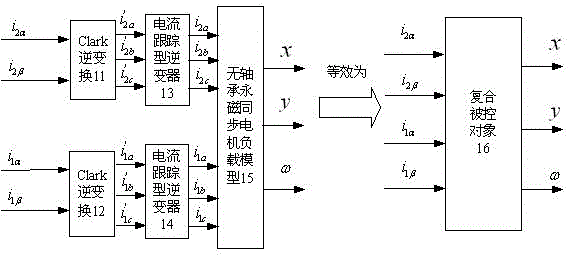
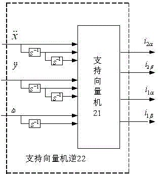
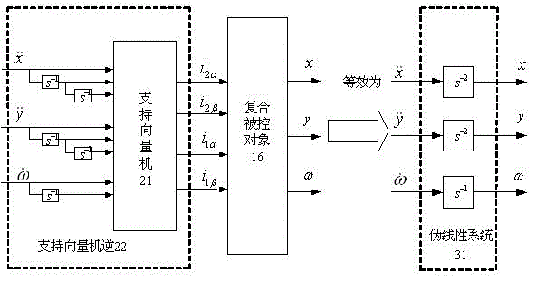
[0017] Embodiments of the present invention are as follows: first, two Clark inverse transforms, two current tracking inverters and bearingless permanent magnet synchronous motor loads are used as a whole to form a composite controlled object, which is equivalent to a 5 The order differential equation model, the relative order of the system vector is {2,2,1}. A support vector machine with 8 input nodes and 4 output nodes plus 5 integrators s -1 Form the inverse of support vector machine for compound plant with 8 input nodes and 4 output nodes. Then the support vector machine is inversely connected before the compound controlled object, and the support vector machine inverse and the compound controlled object are synthesized into two displacement second-order integral subsystems and a rotational speed first-order integral subsystem, thus a complex multivariable , nonlinear, strongly coupled control system is transformed into the control of two second-order integral subsystems...


PUM


Abstract

The invention discloses a construction method for a bearing-less permanent-magnet synchronous motor decoupling controller. Two Clark inverse transformers, two current-tracking inverters, a bearing-less permanent-magnet synchronous motor and a load thereof are integrated to form a compound controlled object, a support vector machine and integrators are used to form a support vector machine inverter, and the support vector machine inverter is connected in series before the compound controlled object, so that a pseudo-linear system consisting of two displacement subsystems and a rotational speed subsystem is composed; according to a linear system design method, the pseudo-linear system is then designed into a linear closed-loop controller, finally, the linear closed-loop controller and the support vector machine inverter are connected with each other in series, and the linear closed-loop controller, the support vector machine inverter, the two Clark inverse transformers and the two current-tracking inverters are used to form a support vector machine inverter controller. The control structure of the controller is simple, the performance of the control system is excellent, and the dynamic decoupling control of the bearing-less permanent-magnet synchronous motor between two degrees of freedom of radial suspending force and between radial suspending force and rotational speed can be realized.

Description

technical field [0001] The invention is a bearingless permanent magnet synchronous motor control system based on a support vector machine inverse, specifically a construction method of a bearingless permanent magnet synchronous motor decoupling controller, which is suitable for high-performance control of a bearingless permanent magnet synchronous motor and belongs to The technical field of electric drive control equipment. Background technique [0002] Bearingless permanent magnet synchronous motor is a new type of motor that applies bearingless technology to ordinary permanent magnet synchronous motors. On the basis of permanent magnet synchronous motors, the magnetic bearing winding (coil) that generates radial suspension force and the motor stator winding Press together to realize the bearingless motor. Bearingless permanent magnet synchronous motor not only has the advantages of high efficiency, high power factor, small size, light weight and good control performance o...

Claims


Application Information

Patent Timeline
Patent Type & Authority Patents(China)
IPC IPC(8): H02P21/00H02P21/13
Inventor 孙晓东陈龙李可杨泽斌朱熀秋
Owner 江苏红光仪表厂有限公司
Why Eureka
Try Eureka