
Numerical control device and control method of numerical control device

A technology of numerical control devices and cutting tools, applied in digital control, program control, computer control, etc., can solve problems such as drive shaft damage, and achieve the effect of avoiding interference and avoiding overtravel

Inactive Publication Date: 2012-11-21
MITSUBISHI ELECTRIC CORP
View PDF14 Cites 16 Cited by
  • Summary
  • Abstract
  • Description
  • Claims
  • Application Information

AI Technical Summary

Problems solved by technology

[0006] If the drive shaft is moved regardless of the occurrence of overtravel, the drive shaft will be damaged due to movement outside the movable range.

Method used


Image

  • Numerical control device and control method of numerical control device
  • Numerical control device and control method of numerical control device
  • Numerical control device and control method of numerical control device

Examples


Embodiment approach 1

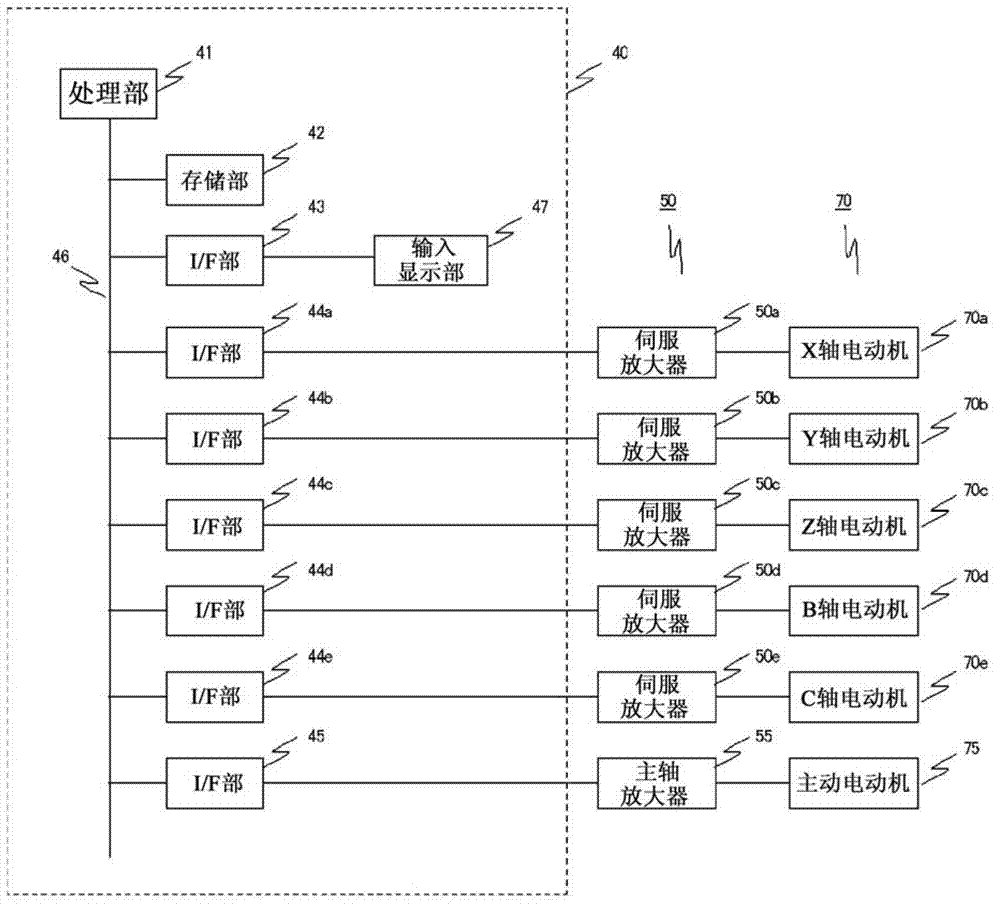
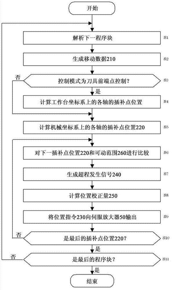
[0049] refer to Figure 1 to Figure 7 , Embodiment 1 will be described.

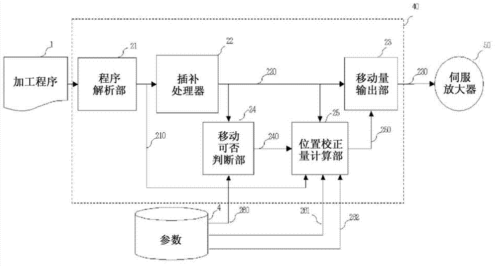
[0050] figure 1 It is a block diagram showing the structure of the numerical control device in Embodiment 1. The numerical control device 40 has a processing unit 41 such as a central processing unit (CPU: Central Processing Unit) and a storage unit 42 such as a read-only memory (ROM: Read-Only Memory) or a random-access memory (RAM: Random-Access Memory). Connection via bus 46 . Various types of data such as a system program, a machining program, and parameters 4 described later are stored in the storage unit 42 . The processing unit 41 executes the machining program according to the system program stored in the storage unit 42 .

[0051] Furthermore, the numerical control device 40 has an I / F unit 43 connected to the bus 46 , I / F units 44 a to 44 e , and an I / F unit 45 , and an input display unit 47 connected to the I / F unit 43 . The input display unit 47 has a keyboard (not shown) for the user t...


PUM


Abstract

Disclosed is a numerical control device provided with a retracted direction determination unit for determining a direction different from a linear axial direction upon which a tool deviates from a movable range as a retraction direction of the tool if the tool is determined to deviate from the movable range; and a tool trace correction unit for correcting a trace of the tool so that, on the basis of the retraction direction, the distance between the tool and the rotational center of the table during when the tool is retracted is greater than or equal to the distance between the tool and the rotational center of the table at the rotation starting time or rotation completion time for the table. According to the disclosed numerical control device, if a table rotation instruction which causes stroke-over to occur upon a linear axis is made while executing control with a coordinate system that is different from the coordinates of a mechanical system, it is possible to avoid stroke-over while avoiding interference between the tool and a work.

Description

technical field [0001] The present invention relates to a numerical control device (NC: Numerical Control) and a control method of the numerical control device, which are used for operations having a plurality of translation axes for moving a tool and a table rotation axis for rotating a table according to a processing program. The machine is controlled, and the tool is used to process the workpiece fixed on the worktable. Background technique [0002] Currently, as a machine tool having a plurality of translation axes for moving a tool and a table rotation axis for rotating a table, for example, Figure 8 or Figure 9 5-axis machine shown. Figure 8 It is an external view of a 5-axis processing machine with three translation axes, one table rotation axis, and one tool rotation axis. Figure 8 In the shown 5-axis processing machine, the tool 102 is moved by three translational axes of the X-axis, Y-axis, and Z-axis that are perpendicular to each other, and the table 101 is r...

Claims


Application Information

Patent Timeline
Patent Type & Authority Applications(China)
IPC IPC(8): G05B19/404G05B19/18
CPCG05B2219/49147G05B19/4061
Inventor 津田刚志佐藤智典小野俊郎藤野大助
Owner MITSUBISHI ELECTRIC CORP
Learn More