
Novel energy-consumption beam falling prevention device

An anti-falling beam, a new type of technology, used in bridges, bridge parts, bridge construction and other directions, can solve the problems of high price and difficult to obtain wide application, and achieve easy material acquisition, simple structure, and energy consumption and energy performance. Effect

Inactive Publication Date: 2014-09-24
南京工大交通科技有限公司
View PDF5 Cites 0 Cited by
  • Summary
  • Abstract
  • Description
  • Claims
  • Application Information

AI Technical Summary

Problems solved by technology

At present, the cable-type anti-fall beam device and oil damper energy-dissipating device are mainly used. The cable-type anti-fall beam device will only work when the relative displacement between the pier (platform) beams exceeds its non-working length. , and can only play a limiting role. Although the oil damper can produce energy consumption, it is difficult to be widely used because it is prone to oil leakage and expensive. The anti-drop beam device that can limit the position has become a top priority

Method used


Image

  • Novel energy-consumption beam falling prevention device
  • Novel energy-consumption beam falling prevention device

Examples


Embodiment Construction

[0025] The present invention will be further described below in conjunction with the accompanying drawings and embodiments.

[0026] as attached Figure 1-3 shown.

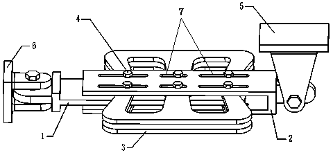
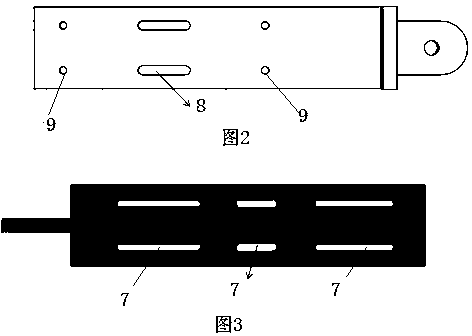
[0027] A new type of energy-dissipating anti-drop beam device, which includes connecting plate A1, connecting plate B2, E-shaped energy-dissipating element 3 (metal materials can be used, such as domestic ordinary Q235 steel), high-strength bolts 4 (standard parts), main beam prefabricated Embedded parts 5 and pier embedded parts 6, such as figure 1 As shown, the connecting plate B2 is provided with a constraint slot 7, such as image 3 As shown, the connecting plate A1 is provided with a constraint slot B8 and a screw hole or a through hole 9, such as figure 2 As shown, the connecting plate B2 is processed with constraining slots 7 matching the number and position of the cantilever limbs of the E-shaped energy dissipation element 3, and the length of the middle constraining slots 7 is less than the length of ...


PUM


Abstract

A new type of energy-consuming beam anti-falling device is characterized by that it includes connecting plate A (1), connecting plate B (2), E-shaped energy-consuming components (3), high-strength bolts (4), and main beam embedded parts ( 5), pier embedded parts (6), constraint slots (7) of connecting plate B (2) and constraining slots (8) of connecting plate A (1), the connecting plate B (2) is processed There are constraint slots (7) matching the number and position of the cantilever limbs of the E-shaped energy dissipating element (3), and the length of the middle constraint slot (7) is less than the length of the constraint slots (7) at both ends; The connecting plate A (1) is processed with a matching constraining slot B (8) at a position opposite to the middle constraining slot (7) on the connecting plate B (2), and a matching constraining slot B (8) is processed at a position opposite to the constraining slots (7) at both ends. Process matching screw holes or through holes (9); connecting plate B (2), connecting plate A (1) and E-shaped energy dissipating element (3) are connected through high-strength bolts (4), connecting plate A (1) The free end of the connecting plate B (2) is hingedly connected to the pier embedded parts (6) through high-strength bolts (4), and the free end of the connecting plate B (2) is hingedly connected to the main beam embedded parts (5). The invention has the characteristics of simple structure, reasonable structural form, low manufacturing cost, easy installation and replacement, excellent energy consumption performance, etc., and has good application prospects.

Description

technical field [0001] The invention relates to a bridge anti-seismic and shock-absorbing technology, especially a novel energy-dissipating anti-drop beam device in the passive energy-dissipating shock-absorbing control and position limiting of bridge structures, specifically a bridge structure that can provide additional damping It is a new type of energy-consuming anti-fall beam device that reduces the seismic response of bridges, limits the relative displacement between pier-beam (or platform-beam), and finally prevents beam fall. Background technique [0002] Aseismic resistance of bridges is a relatively complicated problem. Compared with building structures, due to the structural characteristics of bridges, seismic problems and building structures have their own unique aspects. Expansion joint devices are non-structural components that are designed to accommodate the effects of structural material shrinkage, creep, and external environmental temperature changes. Its n...

Claims


Application Information

Patent Timeline
Patent Type & Authority Patents(China)
IPC IPC(8): E01D19/00
Inventor 徐秀丽李雪红李枝军顾以明许祥
Owner 南京工大交通科技有限公司
Learn More