
Rotary type tubing drain and use method thereof

A technology of oil drainer and rotary type, which is applied in the field of oil drainer, can solve the problems of complex unlocking structure of the oil drainer, and achieve the effects of wide application range, convenient use, and cost reduction

Inactive Publication Date: 2012-11-28
CHINA PETROLEUM & CHEM CORP +1
View PDF3 Cites 4 Cited by
  • Summary
  • Abstract
  • Description
  • Claims
  • Application Information

AI Technical Summary

Problems solved by technology

[0007] One object of the present invention is to provide a rotary oil drainer with simple structure and easy to use, so as to solve the problem of complex unlocking structure of the existing oil drainer

Method used


Image

  • Rotary type tubing drain and use method thereof
  • Rotary type tubing drain and use method thereof

Examples


Embodiment Construction

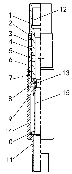
[0021] The specific embodiment of the rotary oil pipe drainer of the present invention is as figure 1 As shown, the oil pipe oil drainer includes an oil drain pipe 1, an oil drain sleeve 6 and a lower joint 11 arranged sequentially from top to bottom. An external thread is provided on the surface, and an internal thread is correspondingly provided in the oil drain sleeve 6, and the oil drain pipe 1 is inserted into the oil drain sleeve 6 to be threadedly connected thereto. Oil drain holes are opened on the side walls of the oil drain pipe 1 and the oil drain sleeve 6 respectively, wherein the inner oil drain hole 5 on the oil drain pipe 1 is lower than the outer oil drain hole 3 on the oil drain sleeve 6 when assembled, and Between the inner oil drain hole 5 and the outer oil drain hole 3, there are two sealing rings 4 on the outer wall of the oil drain pipe 1 for sealing the gap between the oil drain pipe 1 and the oil drain sleeve 6. The inner oil drain hole 5 communicates ...


PUM


Abstract

The invention discloses a rotary type tubing drain and a use method of the rotary type tubing drain, wherein a drain pipe is inserted into a drain sleeve, drain holes which are correspondingly communicated with one another after the drain pipe upwards goes are arranged on the upper-part pipe wall of the drain sleeve and the lower-part pipe wall of the drain pipe, the inner walls arranged at the lower ends of the drain pipe and the drain pipe are provided with clamp grooves which are correspondingly communicated with one another and vertically extend, a locking block for preventing the drain pipe and the drain sleeve from relatively rotating is respectively fixed in each clamp groove by a positioning pin penetrating into the wall of the drain sleeve, and each locking block is provided with a lug boss which is raised out of the inner surface of the drain pipe and used for bearing an impact force to realize the unlocking by shearing off the positioning pin. The drain pipe and the drain sleeve in the tubing drain are in threaded connection with each other and are locked for stopping rotation by the vertical clamp grooves correspondingly arranged between the drain pipe and the drain sleeve and the locking blocks arranged in the clamp grooves, and the unlocking can be realized by the means that a plunger of an oil pump connected on an oil pump rod impacts the locking blocks when the tubing drain is used. The rotary type tubing drain is simple in structure, and convenient to use, so that the use reliability of the tubing drain can be improved.

Description

technical field [0001] The invention belongs to the technical field of oilfield exploitation, and in particular relates to an oil drainer used for draining oil in a pipe string when the oil production pipe string is pulled out and a use method thereof. Background technique [0002] With the continuous improvement of construction civilization requirements and the mandatory implementation of HSE measures, the oilfield has done a lot of work in the field of well site pollution prevention, and it has been continuously strengthened. Among them, the application of the oil drain device in the oil well string is to prevent It is one of the measures to discharge the oil in the oil to the ground, pollute the well site, and reduce the waste of crude oil. Oil drains commonly used in oil fields are as follows: [0003] ①. Anchor type oil drainer, the oil drainer is hydraulic type, which can complete the oil or water draining action at one time and cannot be reused. It is characterized b...

Claims


Application Information

Patent Timeline
Patent Type & Authority Applications(China)
IPC IPC(8): E21B34/12
Inventor 王志清樊琳琳杨康敏孙旭光昝恒毅张朋程连文杨冰郭书强
Owner CHINA PETROLEUM & CHEM CORP
Learn More