A Method of Obtaining Air Leakage of Turbine Shaft Sealing System

A shaft seal system and air leakage technology, which is used in fluid tightness testing, machine/structural component testing, and measuring devices, etc., can solve problems such as difficulty in ensuring steam turbine efficiency and low accuracy in calculating shaft seal air leakage. , to achieve the effect of ensuring safety, efficiency, and accurate reflection

Active Publication Date: 2016-05-11
GUANGDONG ELECTRIC POWER SCI RES INST ENERGY TECH CO LTD
View PDF4 Cites 0 Cited by
  • Summary
  • Abstract
  • Description
  • Claims
  • Application Information

AI Technical Summary

Problems solved by technology

[0005] To sum up, the accuracy of calculating the air leakage of the shaft seal is not high at present, and it is difficult to ensure the efficiency of the steam turbine

Method used


Image

  • A Method of Obtaining Air Leakage of Turbine Shaft Sealing System
  • A Method of Obtaining Air Leakage of Turbine Shaft Sealing System
  • A Method of Obtaining Air Leakage of Turbine Shaft Sealing System

Examples


Embodiment Construction

[0016] In order to facilitate the understanding of the present invention, the following will be described in conjunction with the accompanying drawings.

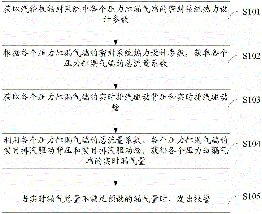
[0017] This invention proposes a method for obtaining the air leakage of the shaft seal system of a steam turbine, please refer to figure 1 , including the steps:

[0018] S101. Obtain the thermal design parameters of the sealing system at the air leakage ends of each pressure cylinder in the shaft sealing system of the steam turbine;

[0019] The thermal design parameters of the sealing system obtained include: the theoretical air leakage volume of each leakage end, the theoretical exhaust driving back pressure of each leakage end, and the theoretical exhaust driving enthalpy of each leakage end.

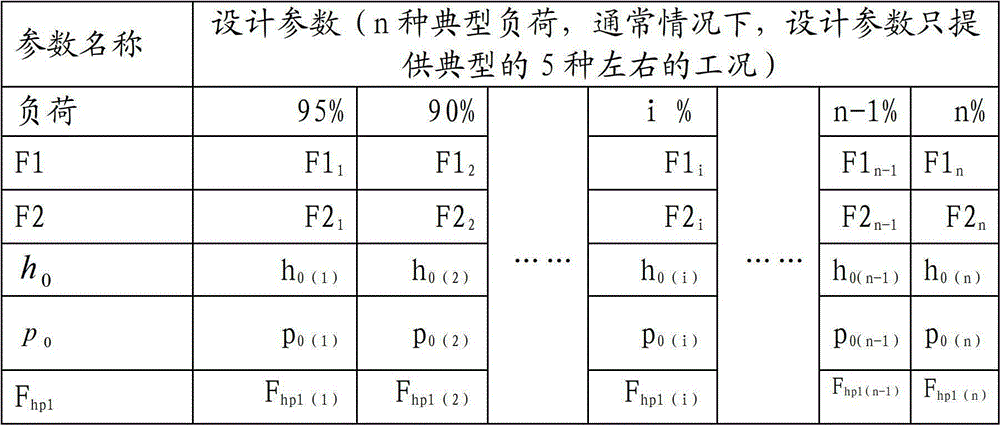
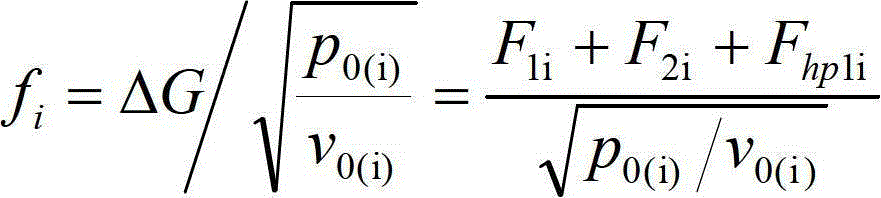
[0020] S102. According to the thermal design parameters of the sealing system at the air leakage end of each pressure cylinder, obtain the total flow coefficient of the air leakage end of each pressure cylinder;

[0021] Specif...


PUM


Abstract

The invention provides a method for acquiring air leakage of a steam turbine shaft seal system. The method comprises the following steps: acquiring sealing system thermal design parameters of each pressure cylinder air leakage end of the steam turbine shaft seal system, wherein the sealing system thermal design parameters comprise the theoretical air leakage of each air leakage end, the theoretical exhaust steam driving back pressure of each air leakage end and the theoretical exhaust steam driving enthalpy of each air leakage end; acquiring the total flow quantity coefficient of each pressure cylinder air leakage end according to the sealing system thermal design parameters of each pressure cylinder air leakage end; acquiring the real-time exhaust steam driving back pressure and the real-time exhaust steam driving enthalpy of each pressure cylinder air leakage end; acquiring the real-time air leakage of each pressure cylinder air leakage end according to the total flow quantity coefficient of each pressure cylinder air leakage end and the real-time exhaust steam driving back pressure and the real-time exhaust steam driving enthalpy of each pressure cylinder air leakage end; and warning when the total quantity of real-time air leakage does not meet the preset air leakage. By the method, the precision of calculating the shaft seal air leakage can be improved and the efficiency of the steam turbine can be guaranteed.

Description

technical field [0001] The invention relates to the control field of a shaft seal system of a steam turbine, in particular to a method for obtaining the air leakage amount of the shaft seal system of a steam turbine. Background technique [0002] The shaft seal system is a special and important link in the steam mass energy balance system. The steam in the turbine moves between the two main parts, the main shaft and the cylinder. Since the main shaft rotates and the cylinder is stationary, there must be a gap between the diaphragm and the main shaft and the top of the moving blades and the cylinder. Since the steam pressure in the cylinder is not equal to the external atmospheric pressure, the high-pressure steam in the steam turbine will leak out from these gaps. In addition, at the high pressure end of the steam turbine or both ends of the high and medium pressure cylinders, where the main shaft passes through the cylinder, steam will also leak outward, which will reduce ...

Claims


Application Information

Patent Timeline
Patent Type & Authority Patents(China)
IPC IPC(8): G01M3/00
Inventor 罗嘉陈世和张曦庞志强孙立明
Owner GUANGDONG ELECTRIC POWER SCI RES INST ENERGY TECH CO LTD
Why Eureka
Try Eureka