
Method and system for diagnosing overheat fault of joints of gas insulated switch equipment bus

A technology for gas-insulated switches and busbar joints, which is applied in the direction of measuring heat, instruments, measuring devices, etc., and can solve the problems of lack of fault judgment criteria and fault type judgment methods, the inability of infrared thermal imaging cameras to achieve online detection, and the discovery of hidden dangers.

Active Publication Date: 2015-05-13
FOSHAN POWER SUPPLY BUREAU GUANGDONG POWER GRID +1
View PDF6 Cites 0 Cited by
  • Summary
  • Abstract
  • Description
  • Claims
  • Application Information

AI Technical Summary

Problems solved by technology

[0004] At present, the operation site mainly uses infrared thermal imaging cameras to carry out regular inspections on gas insulated switchgear, and judges whether overheating faults have occurred based on the comparison between the detected temperature and the temperature of surrounding components. The disadvantages of this method are: ① infrared thermal imaging cameras cannot realize On-line detection makes it difficult to detect hidden dangers in the early stage; ②The detection results are not only related to the detection distance and location, but also affected by the changing ambient temperature and load current, requiring inspection personnel to have rich operating experience and strong subjectivity; ③Lack of effective The fault judgment criterion and fault type judgment method

Method used


Image

  • Method and system for diagnosing overheat fault of joints of gas insulated switch equipment bus
  • Method and system for diagnosing overheat fault of joints of gas insulated switch equipment bus
  • Method and system for diagnosing overheat fault of joints of gas insulated switch equipment bus

Examples


Embodiment Construction

[0031] The present invention will be described in further detail below in conjunction with the embodiments and accompanying drawings, but the embodiments of the present invention are not limited thereto.

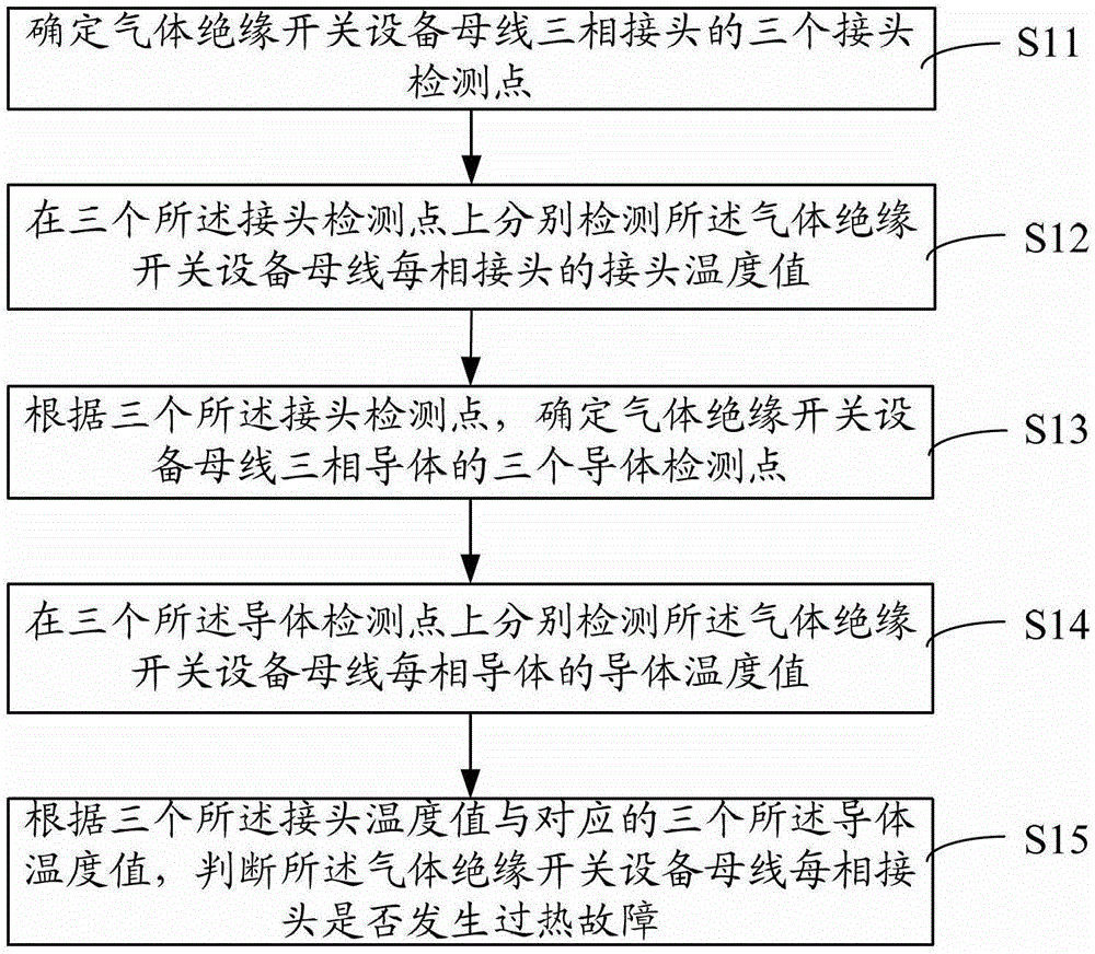
[0032] like figure 1 As shown, it is a schematic flow chart of a preferred embodiment of the gas insulated switchgear bus joint overheat fault diagnosis method of the present invention, including:

[0033] S11. Determine the three joint detection points of the gas-insulated switchgear busbar three-phase joint;

[0034] The temperature change of the three-phase joint is the basis for judging the overheating fault of the joint. As the temperature of the joint rises, the heat is transferred from the joint to the busbar shell by natural convection and heat radiation. Therefore, it is necessary to determine three joint detection points on the busbar shell for Collect the temperature change of each phase joint;

[0035] In a preferred embodiment, step S11 may include:

[0036] ...


PUM


Abstract

The invention discloses a method for diagnosing overheat fault of joints of a gas insulated switch equipment bus. The method comprises the following steps: determining three joint detection points of three-phase joints of the gas insulated switch equipment bus and detecting the joint temperature value of each phase joint of the gas insulated switch equipment bus respectively; determining three conductor detection points of three-phase conductors of the gas insulated switch equipment bus according to the three joint detection points and detecting the conductor temperature value of each phase conductor of the gas insulated switch equipment bus respectively; and judging each phase joint of the gas insulated switch equipment bus is in overheat fault or not according to the temperature value of the three joints and the temperature value of the three corresponding conductors. Correspondingly, the invention also provides a system for diagnosing the overheat fault of the joints of the gas insulated switch equipment bus. By the method and the system, the overheat fault of the bus joints can be judged, the fault type of the three-phase joints can be determined and the diagnosis result is not influenced by the environmental factor.

Description

technical field [0001] The invention relates to the field of fault diagnosis of electrical equipment, in particular to a method for diagnosing an overheating fault of a bus joint of a gas-insulated switchgear and a system for diagnosing an overheating fault of a bus joint of a gas-insulated switchgear. Background technique [0002] Gas insulated switchgear has the advantages of small footprint, high reliability, less maintenance, and long service life. It has been widely used in power transmission and distribution systems at home and abroad. However, due to the lack of strict quality control in manufacturing, on-site installation, and acceptance, the overheating or even burning of the busbar of gas-insulated switchgear due to excessive contact resistance of the joints seriously affects the reliability and stability of the power supply of the power grid. [0003] When the contact of the gas-insulated switchgear busbar joints deteriorates, the contact heat loss increases, the ...

Claims


Application Information

Patent Timeline
Patent Type & Authority Patents(China)
IPC IPC(8): G01R31/00G01K11/00
Inventor 苏杏志陈勉舒乃秋谢志杨金向朝吴晓文张乾良章涛李洪涛李玲李红玲关向雨
Owner FOSHAN POWER SUPPLY BUREAU GUANGDONG POWER GRID
Learn More