coaxial connector with switch

A technology of coaxial connectors and switches, applied in the direction of connection, fixed connection, bipolar connection, etc., can solve the problems of production degradation, cost increase, ground wire fixing troubles such as parts processing costs and assembly costs, and achieve miniaturization , Increase the processing fee and reduce the cost

Inactive Publication Date: 2014-10-22
SMK CO LTD
View PDF5 Cites 0 Cited by
  • Summary
  • Abstract
  • Description
  • Claims
  • Application Information

AI Technical Summary

Problems solved by technology

[0013] (1) Due to the fitting part of the probe 11, the mechanism part of the switch, the normally closed terminal or the fixing part on the printed circuit board 12 of the common terminal station, etc., the structural parts of the conventional coaxial connector 9 with a switch are all mounted on the printed circuit board. on the circuit board 12, so the height of the conventional coaxial connector 9 with a switch remains unchanged as the installation height h, which becomes an obstacle to the miniaturization of small electronic equipment
[0014] (2) When the size of the conventional coaxial connector 9 with a switch is excessively reduced for the miniaturization of small electronic devices, the productivity of parts such as processing costs and assembly costs deteriorates due to the miniaturization and complexity of each part. , which becomes the cause of cost increase
[0015] (3) In order to suppress the mounting height h of the conventional coaxial connector with switch 9, it is considered to open a hole on the printed circuit board 12 to fit the conventional coaxial connector with switch. The conventional coaxial connector 9 with a switch requires complex hole processing, and the connection of the ground wire and the fixing on the printed circuit board 12 are troublesome.

Method used


Image

  • coaxial connector with switch
  • coaxial connector with switch
  • coaxial connector with switch

Examples


Embodiment 1

[0044] based on Figure 1 to Figure 5 Example 1 of the present invention will be described.

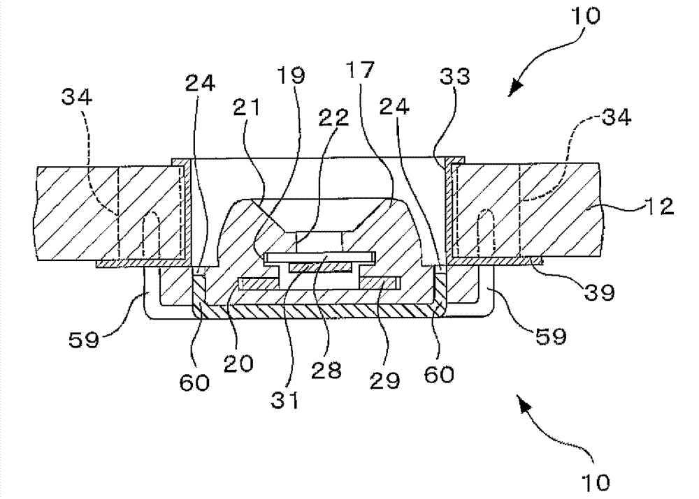
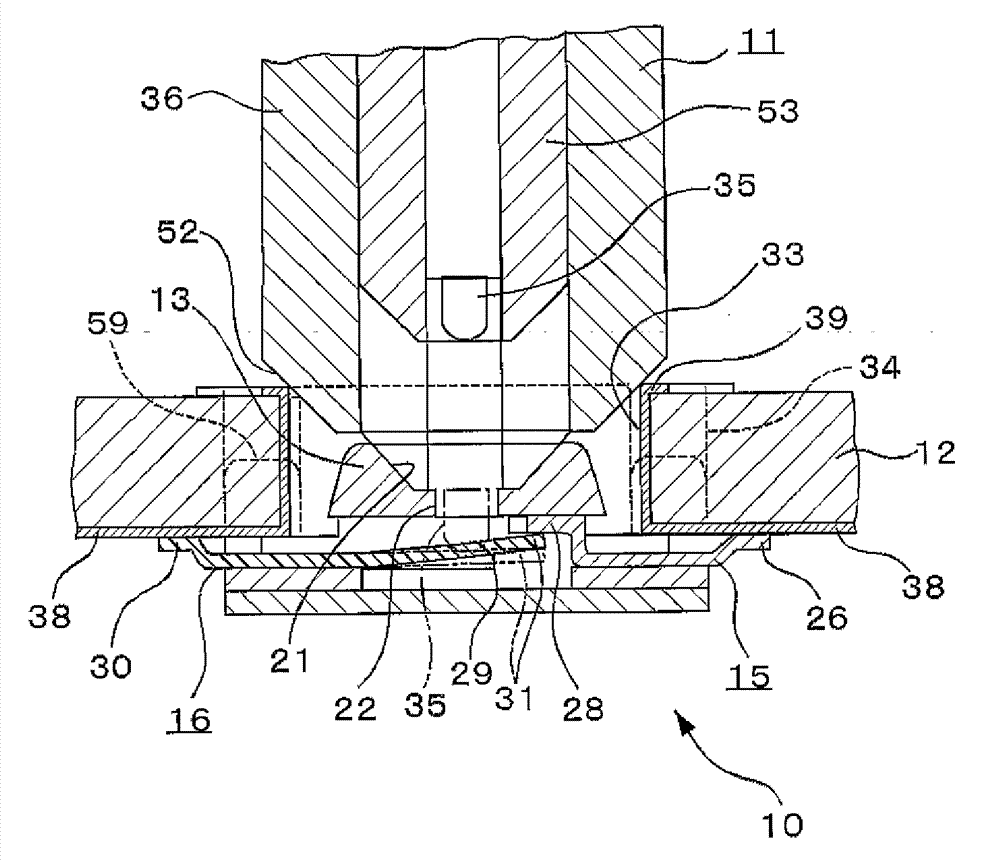
[0045] exist Figure 4 Among them, the coaxial connector 10 with a switch of the present invention is composed of a housing 13 made of an insulating material such as a plastic material, an outer cover 14 formed by pressing a conductive metal plate, and a switch mechanism. The housing 13 is The upper part is in the shape of a cone for guiding the probe 11, and the lower part is in the shape of a quadrangular plate. The overall height is as low as possible. A terminal, specifically a normally closed terminal 15 and a common terminal 16.

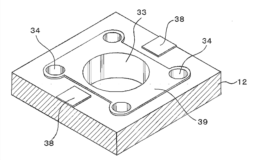
[0046] The coaxial connector with switch 10 of the present invention is fitted and fixed on the printed circuit board 12 from the lower surface.

[0047] Above-mentioned casing 13 is made up of the guide cylinder part 17 that overall height is lower than above-mentioned printed circuit board 12 in the upper half, and the substrate part 18 of quadril...


PUM


Abstract

The invention relates to a coaxial connector with a switch. The coaxial connector can reduce the installation height on a printed circuit, simplify the shapes of various parts, improve the performance stability, and reduce the cost. The inside of a housing (13) is provided with a switch mechanism which is arranged on a printed circuit board (12). The coaxial connector turns on and turns off the switch mechanism via a probe (11). The housing (13) is provided with a guide cylinder (33) with the lower surface being embedded in a guide cylinder through hole of the printed circuit board (12), and the insertion of a contact pin (35) of the probe (11) on one side of the upper surface of the guide cylinder makes terminals (15, 16) become close with or far away from each other. The housing (13) also includes a substrate part (18) which is formed into one body with the guide cylinder (17) and is fixed through pressing against the lower surface of the printed circuit board. The substrate part (18) enables connecting terminal parts (26, 30) of the terminals (15, 16) of the switch mechanism to be connected with the printed circuit board (12).

Description

technical field [0001] The present invention relates to a connector built into a small electronic device such as a cellular phone, which reduces the mounting height on a printed circuit board and simplifies the structure of each part. Background technique [0002] Conventional coaxial connectors with switches 9 such as Figure 6 as well as Figure 7 As shown, the housing 40 made of plastic material and the like, the cover 41 of the conductive metal plate, and the normally closed terminal 42 and the common terminal 43 of the conductive metal plate are configured so that the overall height is as low as possible (Patent Document 1). [0003] The housing 40 is a cylindrical part 44 with an overall height in the upper half, and a quadrangular plate shape with an overall height in the lower half through the terminal supporting protrusions 46 protruding slightly to the left and right and the anti-rotation protrusions 47 protruding slightly to the front and rear. . A pin insertion...

Claims


Application Information

Patent Timeline
Patent Type & Authority Patents(China)
IPC IPC(8): H01R13/502H01R13/70H01R12/51
CPCH01R13/71H01R24/40H01R24/46H01R2103/00
Inventor 梁濑智康富樫晃司
Owner SMK CO LTD
Why Eureka
Try Eureka