Roller element of tripod joint and tripod joint

A rolling element, three-pin shaft technology, applied in couplings, elastic couplings, mechanical equipment, etc., can solve problems such as infeasibility and cost

Active Publication Date: 2015-06-24
VOLKSWAGEN AG
View PDF8 Cites 0 Cited by
  • Summary
  • Abstract
  • Description
  • Claims
  • Application Information

AI Technical Summary

Problems solved by technology

In this case it is necessary to remove the shaft ring, which is sometimes not feasible or involves great expense

Method used


Image

  • Roller element of tripod joint and tripod joint
  • Roller element of tripod joint and tripod joint
  • Roller element of tripod joint and tripod joint

Examples


Embodiment Construction

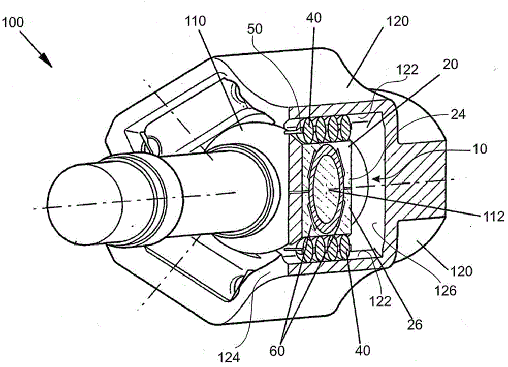
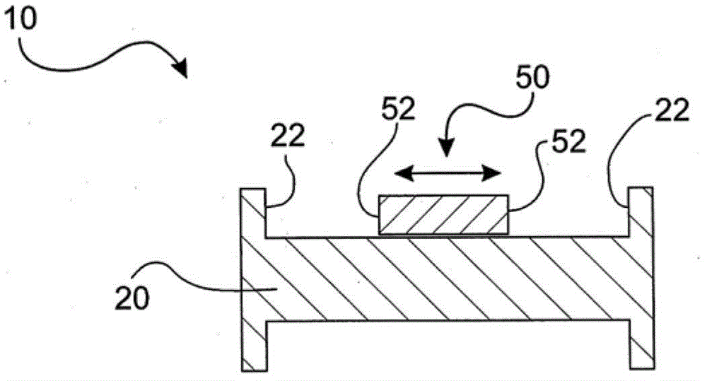
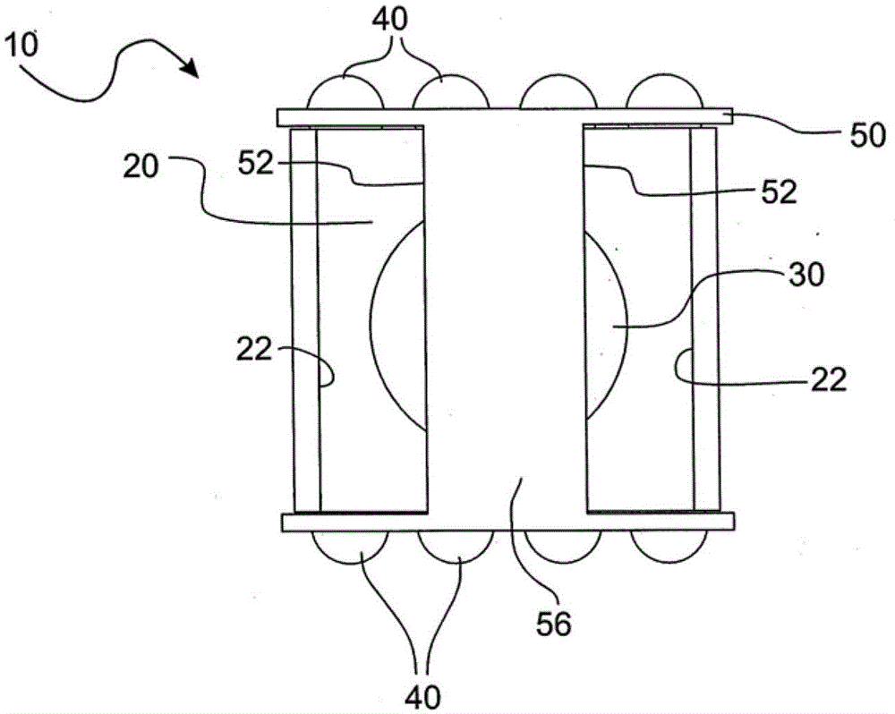
[0032] according to figure 1 The three-pin universal joint 100 of the present invention and the arrangement of the three-pin universal joint 100 of the present invention are briefly shown. The tripod joint 100 has a joint outer member 120 that surrounds the tripod drive shaft and thus also surrounds the tripod assembly 110 . To this end, the joint outer part 120 has a pot-shaped recess into which the tripod assembly 110 protrudes. The three-pin shaft assembly 110 in this embodiment has three pin shafts 112 respectively supported by the rolling elements 10 of the present invention. In this case, the bottom surface 126 and the end surface 124 are defined by the pot-shaped structure of the joint outer part 122 . The rolling element 10 of this embodiment is designed as a linear guide and accommodates a pin 112 of a tripod assembly 110 in its central receiving opening 30 . Housing 20 , in which receiving bore 30 is formed, is supported via rolling bodies 40 on raceway 122 in out...


PUM


Abstract

The element (10) has a housing (20) with a retaining opening that supports a pin (112) of a tripod star (110). Rolling bodies (40) are attached with the housing for supporting the housing on mutually opposite tracks (122) of a joint outer part (120) of a tripod joint (100). The rolling bodies are held by a retainer (50) translationally movable relative to the housing. The housing and the retainer comprise two sets of stop surfaces, which are formed such that end positions of the retainer are defined relative to the housing. The rolling bodies are formed in sphere, cylinder and barrel shapes. An independent claim is also included for a tripod joint.

Description

technical field [0001] The invention relates to a rolling element of a three-pin shaft universal joint and a three-pin shaft universal joint with the rolling element. Background technique [0002] Rolling elements and tripod joints with rolling elements are known. They are used in order to be able to compensate axial and angular misalignments between two rotating shafts. Here, the tripod shaft type universal joint is equipped with a universal joint outer shaft and a tripod shaft transmission shaft. The three-pin assembly of the three-pin drive shaft is supported inside the universal joint outer part of the universal joint outer shaft. The bearing is designed in such a way that the tripod drive shaft can be both axially displaced and tilted. This enables axial compensation via the rolling elements and tilt compensation via the pivot connection. The use of such rolling bodies in linear guides has also been proposed. [0003] Such rolling elements and tripod joints are kno...

Claims


Application Information

Patent Timeline
Patent Type & Authority Patents(China)
IPC IPC(8): F16D3/205F16D3/22
CPCF16D3/2055F16D2003/2023
Inventor M.佐恩哈根A.米克
Owner VOLKSWAGEN AG
Why Eureka
Try Eureka