Visual slide rheostat

A sliding wire resistance, intuitive technology, applied in the direction of sliding contact resistors, etc., can solve the problems of the user's other operation influence, the user's frequent viewing and other problems

Inactive Publication Date: 2012-12-05
TAIZHOU SHUANGYU ELECTRONICS
View PDF0 Cites 0 Cited by
  • Summary
  • Abstract
  • Description
  • Claims
  • Application Information

AI Technical Summary

Problems solved by technology

Its disadvantage is that it requires the user to frequently check the scale that the slider is aimed at, thus affecting other operations of the user

Method used


Image

  • Visual slide rheostat

Examples


Embodiment Construction

[0011] The following descriptions are only preferred embodiments of the present invention, and therefore do not limit the protection scope of the present invention.

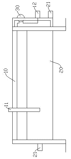
[0012] Examples, see figure 1 Shown: intuitive sliding wire resistance, including resistance wire 20 and guide rail 10. A slide block 11 is provided on the guide rail 10 , and the slide block 11 is connected with an intermediate terminal 12 . Of course, the slider 11 is slidably connected to the resistance wire 20 . Meanwhile, at least one end of the resistance wire 20 is connected with a resistance wire terminal 21 . In this way, as the slider 11 moves, the resistance value between the intermediate terminal 12 and the resistance wire terminal 21 changes. In order to facilitate the user to intuitively understand the change of the resistance value, the guide rail 10 and the intermediate terminal 12 are connected through the display lamp 30 . In this way, with the change of the resistance value of the sliding w...


PUM


Abstract

The invention discloses a visual slide rheostat which comprises a resistance wire and a guide rail. A slider connected with a middle binding post is arranged on the guide rail, at least one end of the resistance wire is connected with a resistance wire binding post, and the guide rail and the middle binding post are connected with each other through a display lamp. The visual slide rheostat has the advantage that users can conveniently and visually know resistance change conditions while other operations are unaffected.

Description

technical field [0001] The invention relates to the technical field of electronic components, in particular to an intuitive sliding wire resistor. Background technique [0002] Sliding wire resistors are electronic components commonly used in laboratories and power systems. Generally, in the process of use, in order to understand the change of resistance, a scale plate is usually set on the side of the sliding wire resistance. In this way, by looking at the scale aligned with the slider on the guide rail, the change of resistance can be grasped. The disadvantage is that the user is required to frequently check the scale to which the slider is aligned, thereby affecting other operations of the user. Therefore it is necessary to improve it. Contents of the invention [0003] In view of the shortcomings of the above-mentioned prior art, the purpose of the present invention is to provide an intuitive sliding wire resistance, which is convenient for users to understand the c...

Claims


Application Information

Patent Timeline
Patent Type & Authority Applications(China)
IPC IPC(8): H01C10/38
Inventor 阮献忠
Owner TAIZHOU SHUANGYU ELECTRONICS
Why Eureka
Try Eureka