Dynamic rapid positioning device and method of using the same

A technology of positioning device and power device, applied in the direction of positioning device, clamping, support, etc., can solve the problems of a lot of time adjustment, alignment, low equipment utilization, poor safety and reliability, etc., and achieve easy to master, improve work efficiency, The effect of quick positioning

Inactive Publication Date: 2015-09-23
LINYI SHENGDAI MACHINERY CO LTD
View PDF7 Cites 0 Cited by
  • Summary
  • Abstract
  • Description
  • Claims
  • Application Information

AI Technical Summary

Problems solved by technology

[0004] The purpose of the present invention is to provide a dynamic rapid positioning device and its use method to solve the problem that in the prior art, when processing structural parts, it takes a lot of time to adjust and align, resulting in low equipment utilization, low work efficiency, safety and reliability. poor sex defect

Method used


Image

  • Dynamic rapid positioning device and method of using the same
  • Dynamic rapid positioning device and method of using the same
  • Dynamic rapid positioning device and method of using the same

Examples


Embodiment 1

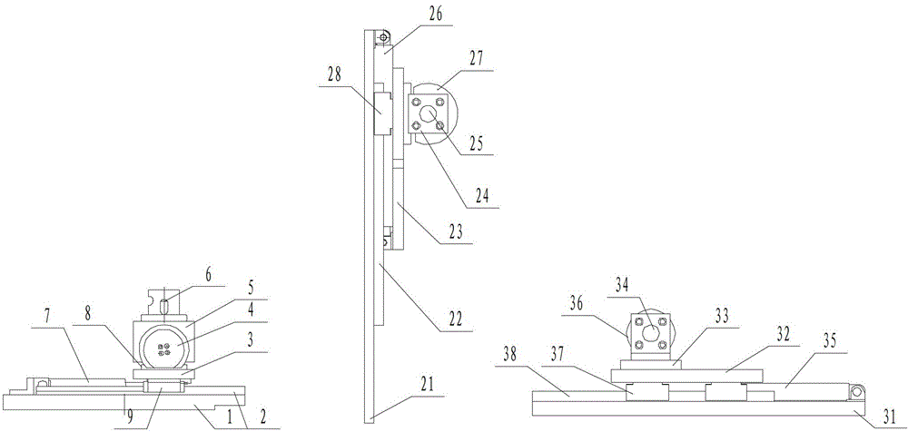
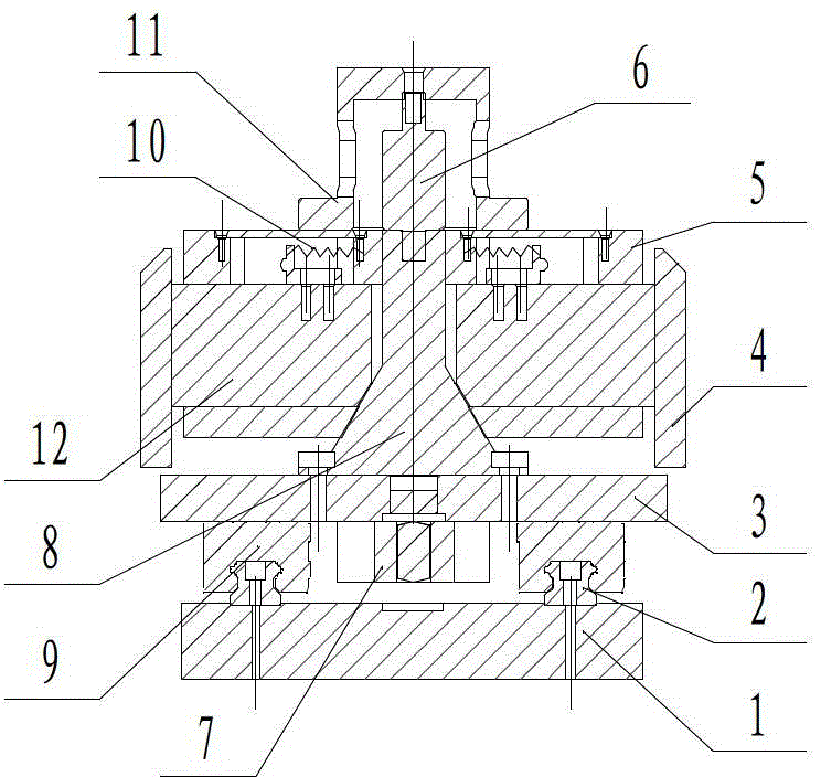
[0035] A dynamic fast positioning device, including fast front positioning, fast middle positioning and fast rear positioning; fast front positioning includes a front base plate 1, a front moving plate 3 and a forward oil cylinder 7, and the front base plate 1 is provided with a front rail 2, and the front moving The board 3 is provided with a front box body 5, a front top oil cylinder seat 11, a front top oil cylinder 6, a front guide positioning shaft 8, a return spring 10 and a front travel device 9, and two slide bars 12 are arranged symmetrically in the front box body 5. , the front positioning block 4 is fixed on the slide bar 12;

[0036] The fast mid-positioning includes mid-sole plate 21, mid-moving plate 23, mid-feed cylinder 26 and mid-horizontal oil cylinder 25. Mid-sole plate 21 is provided with mid-track 22, mid-sole plate 23 is provided with mid-moving device 28 and two mid-positioning units. Block 27; Fast rear positioning includes rear base plate 31, rear movi...

Embodiment 2

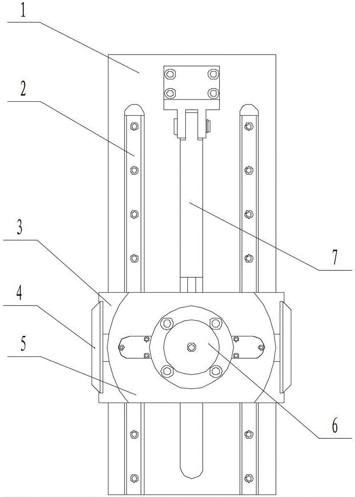
[0039] The front track 2, the middle track 22 and the rear track 38 are all racks, and the front traveling device 9, the middle traveling device 28 and the rear traveling device 37 are all gears, and the gears are respectively installed and fixed on the front moving plate 3 and the middle by the shaft and the shaft seat. On moving plate 23 and rear moving plate 32, others are identical with embodiment 1.


PUM


Abstract

The invention discloses a dynamic quick positioning device and an application method thereof, and belongs to the field of manufacture of machinery. The dynamic quick positioning device overcomes shortcomings of low equipment utilization rate and work efficiency and poor safety and reliability due to the fact that a large amount of time is required for adjusting and aligning a structural part when the structural part is machined in the prior art. The application method mainly includes steps of quick front positioning, quick middle positioning and quick rear positioning. The dynamic quick positioning device is mainly used for machining and manufacturing large long rod-shaped structural parts.

Description

technical field [0001] The invention relates to the field of mechanical manufacturing, in particular to a dynamic quick positioning device used when machining structural parts. Background technique [0002] Most of the two-axis machining centers are equipped with two worktables, which can be used interchangeably. They are especially good at traversing, milling, and cutting symmetrically configured holes. They are suitable for machining long rod-shaped structural parts, such as booms and buckets of excavators, etc. . However, when the long rod-shaped structural member is processed, its positioning position is inconsistent with the processing position. During the clamping process, in order to avoid the spatial position of the tool, the existing tooling clamping position dare not choose the machining position. In order to facilitate machining, the current practice is to design clamping tooling, clamp the structural parts, and perform machining after adjustment. Since each str...

Claims


Application Information

Patent Timeline
Patent Type & Authority Patents(China)
IPC IPC(8): B23Q3/18
Inventor 王德军洪峰
Owner LINYI SHENGDAI MACHINERY CO LTD
Why Eureka
Try Eureka