Injection molding apparatus and method for automatic cycle to cycle cavity injection

a technology of injection molding and automatic cycle, which is applied in the direction of process and machine control, flow control without auxiliary power, instruments, etc., can solve the problems of air bubbles or surface defects in the molded parts, and achieve the effect of reducing the need, facilitating automatic set-up, monitoring and/or adjustment, and reducing the need

Active Publication Date: 2018-01-25
SYNVENTIVE MOLDING SOLUTIONS INC
View PDF1 Cites 1 Cited by
  • Summary
  • Abstract
  • Description
  • Claims
  • Application Information

AI Technical Summary

Benefits of technology

[0005]In various embodiments, the invention relates to an apparatus and method for triggering the opening of multiple gates to a single mold cavity of an injection molding system. In contrast to the prior art valve gating systems that depend on a preset time or screw position, in one embodiment the present invention utilizes a new apparatus and method of triggering based on flow front detection in the cavity coupled with detection by position sensors of the actual time of valve pin withdrawal from the respective gate. In another embodiment the invention utilizes triggering based on a start of injection cycle or a position of a screw barrel that feeds fluid material to an injection molding system, coupled with detection by position sensors of the actual time of valve pin withdrawal from the respective gate. These embodiments enable automatic adjustments to be made on subsequent injection cycles. The invention thus facilitates automatic set-up, monitoring and / or adjustment of the sequential valve gating process and reduces the need for highly experienced operators.

Problems solved by technology

Otherwise, air bubbles or surface defects in the molded part will occur.

Method used


Image

  • Injection molding apparatus and method for automatic cycle to cycle cavity injection
  • Injection molding apparatus and method for automatic cycle to cycle cavity injection
  • Injection molding apparatus and method for automatic cycle to cycle cavity injection

Examples


Embodiment Construction

[0104]Various embodiments of the present invention are now described with reference to the drawings. In the following description, for purposes of explanation, numerous specific details are set forth in order to provide a thorough understanding of one or more implementations of the present invention. It will be evident, however, that the present invention may be practiced without these specific details. In other instances, well-known structures and devices are shown in block diagram form in order to facilitate describing the present invention.

Sequential Valve Gating Apparatus and Method

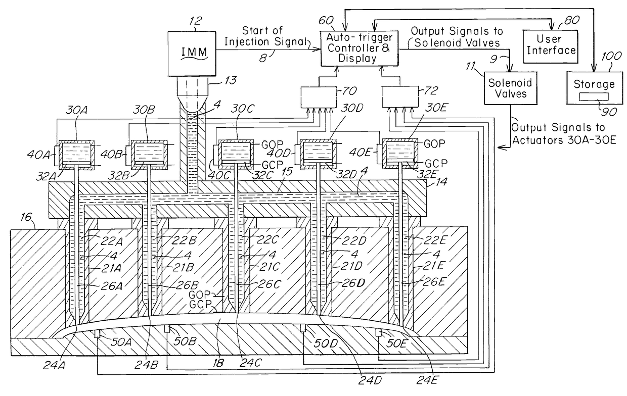
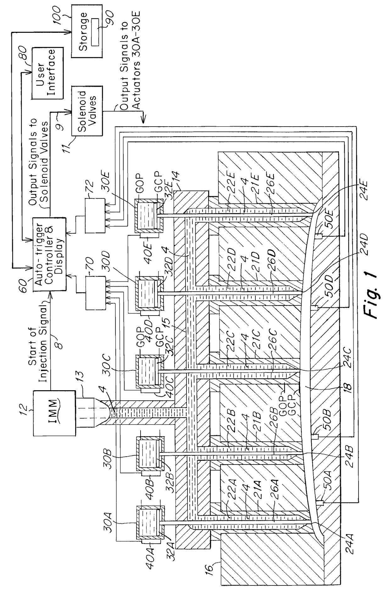
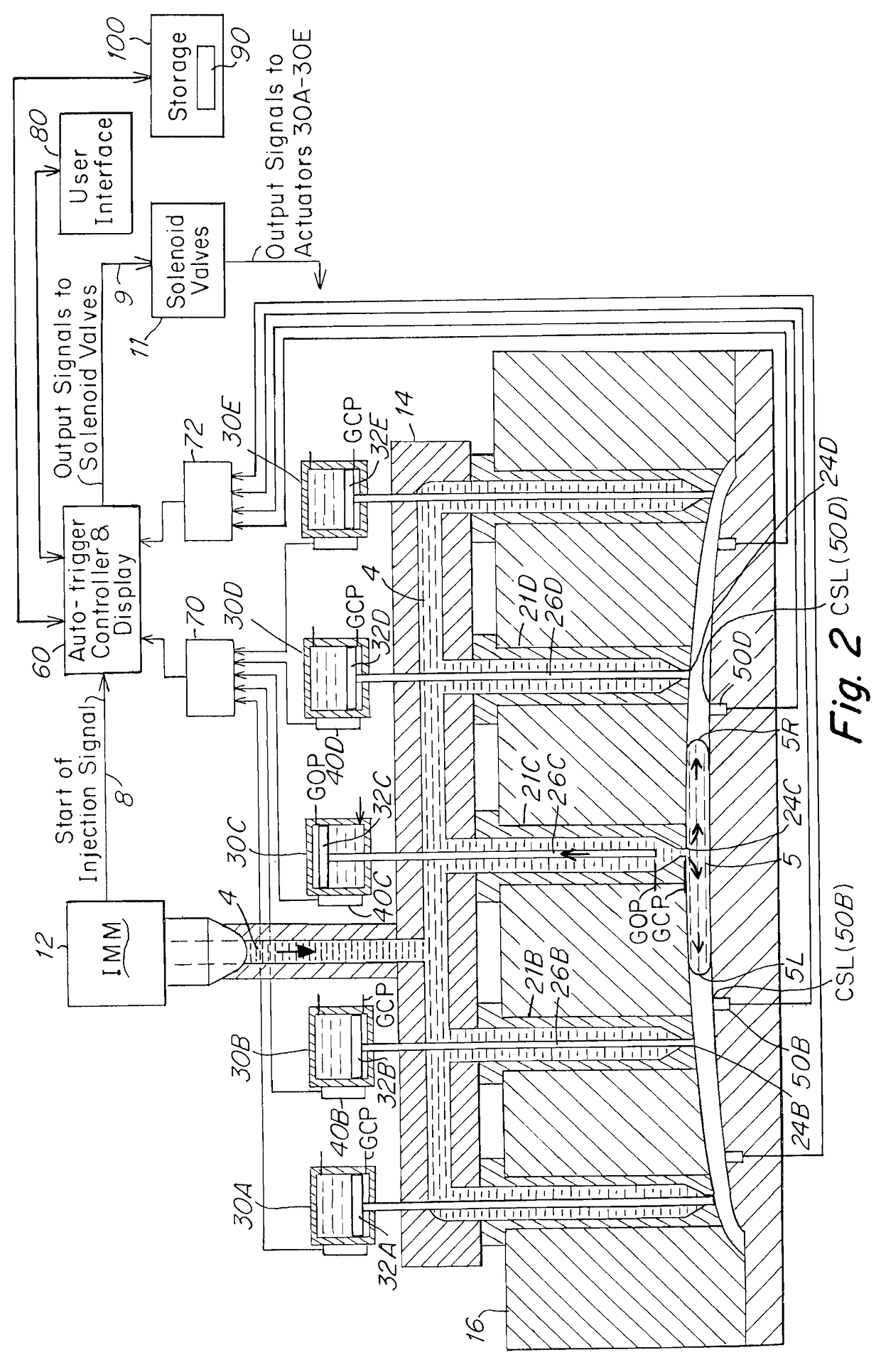
[0105]FIG. 1 is a schematic view of a plastic injection molding apparatus for implementing a sequential valve gating process according to one embodiment of the invention. The injection molding system (IMM) 10 includes an injection molding machine 12, a manifold 14, a mold 16 having a mold cavity 18, a valve gating system 20 including a plurality of nozzles 21 that feed the single mold cavity, an actua...


PUM

PropertyMeasurementUnit
instruction timeaaaaaaaaaa
fluid propertyaaaaaaaaaa
timeaaaaaaaaaa

Abstract

An injection molding system comprising:
    • a first selected valve,
    • one or more downstream valves, delivering a fluid to a mold cavity,
    • at least one fluid property sensor that detects a flow front of fluid material flowing downstream through the mold cavity at a trigger location within the cavity disposed between the first gate and at least one selected downstream gate,
    • a controller instructing an actuator associated with the downstream gates to open the gates at a predetermined open gate target time on a first injection cycle,
    • each valve associated with a position sensor that detects opening of a gate at an actual open gate time to the controller,
    • the controller automatically adjusting time of instruction to open the gates on a subsequent injection cycle by an adjustment time equal to any delay in time between the predetermined open gate target time and the actual open gate time.

Description

RELATED APPLICATIONS[0001]This application is a continuation of and claims the benefit of priority to PCT / US17 / 043029 filed Jul. 20, 2017 which in turn claims the benefit of priority to U.S. Application Ser. No. 62 / 364,488, filed 20 Jul. 2016 the disclosures of both of which are incorporated by reference as if fully set forth in its entirety herein.[0002]The disclosures of all of the following are incorporated by reference in their entirety as if fully set forth herein: U.S. Pat. No. 5,894,025, U.S. Pat. No. 6,062,840, U.S. Pat. No. 6,294,122, U.S. Pat. No. 6,309,208, U.S. Pat. No. 6,287,107, U.S. Pat. No. 6,343,921, U.S. Pat. No. 6,343,922, U.S. Pat. No. 6,254,377, U.S. Pat. No. 6,261,075, U.S. Pat. No. 6,361,300 (7006), U.S. Pat. No. 6,419,870, U.S. Pat. No. 6,464,909 (7031), U.S. Pat. No. 6,599,116, U.S. Pat. No. 7,234,929 (7075US1), U.S. Pat. No. 7,419,625 (7075US2), U.S. Pat. No. 7,569,169 (7075US3), U.S. patent application Ser. No. 10 / 214,118, filed Aug. 8, 2002 (7006), U.S. P...

Claims


Application Information

Patent Timeline
Patent Type & Authority Applications(United States)
IPC IPC(8): B29C45/13G05D7/01B29C45/27B29C45/76B29C45/28
CPCB29C45/13B29C45/762B29C45/281B29C45/2703B29C45/2725G05D7/0113B29C2045/279B29C2945/76056B29C2945/76381B29C2945/76555B29C2945/76558B29C2945/76859B29C45/77B29C2045/0032B29C2045/2865B29C2945/76043B29C2945/7607B29C2945/76086B29C2945/76093B29C2945/76167B29C2945/76187B29C2945/76287B29C2945/76454B29C2945/76488B29C2945/76648B29C2945/76936G05D7/0635B29C2945/76876
Inventor MOSS, MARK
Owner SYNVENTIVE MOLDING SOLUTIONS INC
Why Eureka
Try Eureka