Water injection packer

A packer and center pipe technology, applied in the field of water injection packers, can solve problems such as difficult manufacturing and processing, complex structural design, unfavorable well washing and oil and gas production

Inactive Publication Date: 2012-12-12
杨成伟
View PDF0 Cites 0 Cited by
  • Summary
  • Abstract
  • Description
  • Claims
  • Application Information

AI Technical Summary

Problems solved by technology

[0002] Most of the current packers are mechanical, and their structural design is relatively complicated, and the manufacturing and processing are difficult.

Method used


Image

  • Water injection packer

Examples


Embodiment Construction

[0011] Any feature disclosed in this specification (including any appended claims, abstract and drawings), unless expressly stated otherwise, may be replaced by alternative features which are equivalent or serve a similar purpose. That is, unless expressly stated otherwise, each feature is one example only of a series of equivalent or similar features.

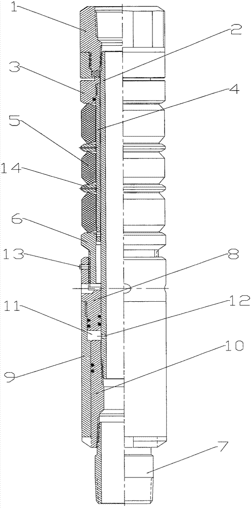
[0012] Such as figure 1 As shown, a water injection packer of the present invention includes an upper joint 1, a central pipe 2, an upper rubber sleeve seat 3, a rubber sleeve liner 4, a rubber sleeve 5, a lower rubber sleeve seat 6, and a lower joint 7, wherein the central pipe The upper end of 2 is connected with the upper joint 1, the lower end of the central tube 2 is connected with the lower joint 7, the rubber tube liner 4 is set outside the central tube 2, the rubber tube 5 is set outside the rubber tube liner 4 and is located at the upper rubber tube seat 3 Between the center tube 2 and the lower rubber tube seat 6, t...


PUM


Abstract

The invention discloses a water injection packer which comprises an upper joint, a central pipe, an upper rubber barrel seat, a rubber barrel liner pipe, a rubber barrel, a lower rubber barrel seat and a lower joint. A piston ring is connected at the lower end of the lower rubber barrel seat outside the central pipe, a piston is connected outside the piston ring, a hydraulic cylinder is connected outside the central pipe in the piston, and a hydraulic cavity is formed among the piston ring, the piston, the hydraulic cylinder and the central pipe. Therefore, the rubber barrel can be compressed to deform by water injection, and packing effect is achieved.

Description

technical field [0001] The invention relates to a packer, in particular to a water injection packer. Background technique [0002] Most of the current packers are mechanical, and their structural design is relatively complicated, and the manufacturing and processing are difficult. It is not very convenient to operate during operation, and the sealing effect is not good, which is not conducive to well washing and oil and gas production. Contents of the invention [0003] The technical problem to be solved by the present invention is to provide a water injection packer with simple structural design and good sealing effect. [0004] In order to solve the above technical problems, the present invention adopts the following technical scheme: a water injection packer, including an upper joint, a central pipe, an upper rubber sleeve seat, a rubber sleeve liner, a rubber sleeve, a lower rubber sleeve seat, and a lower joint, wherein the center The upper end of the pipe is connect...

Claims


Application Information

Patent Timeline
IPC IPC(8): E21B33/126
Inventor 杨成伟
Owner 杨成伟
Why Eureka
Try Eureka