A gas drainage and sealing device

A sealing device and gas drainage technology, which is applied in sealing/isolation, wellbore/well components, earthwork drilling and production, etc., can solve the problem of high unit price of polyurethane sealing fluid, unusable sealing, and serious gas leakage To improve the quality and efficiency of sealing holes, reduce the cost of sealing holes, and increase the concentration

Inactive Publication Date: 2017-02-01
SHANDONG UNIV OF SCI & TECH
View PDF6 Cites 0 Cited by
  • Summary
  • Abstract
  • Description
  • Claims
  • Application Information

AI Technical Summary

Problems solved by technology

It is difficult to evenly send polyurethane sealing fluid into the drill hole. The unit price of polyurethane sealing fluid is relatively high, and the amount used in the sealing process is relatively large, so the cost of sealing holes with this technology is relatively high
Mechanical elastic hole sealing and inflatable hole sealing methods have poor sealing performance and serious air leakage, and basically cannot be used for long-term drainage drilling in this coal seam.
The cost of the hydraulic expansion sealing method is relatively high, and the micro-leakage of the sealer cannot guarantee the effect of long-term sealing
When using cement slurry to seal the hole, because polyurethane sealing fluid is used to seal the gap between the two ends of the casing and the wall of the drilled hole, it also has the disadvantage of using polyurethane sealing fluid for hole sealing
Using the existing sealing device to seal the hole has the disadvantages of serious air leakage, poor quality, high cost and long sealing time.

Method used


Image

  • A gas drainage and sealing device
  • A gas drainage and sealing device

Examples


Embodiment Construction

[0014] The present invention provides a gas drainage and sealing device. In order to make the purpose, technical solution and effect of the present invention clearer and clearer, the present invention will be further described in detail below. It should be understood that the specific embodiments described here are only used to explain the present invention, not to limit the present invention.

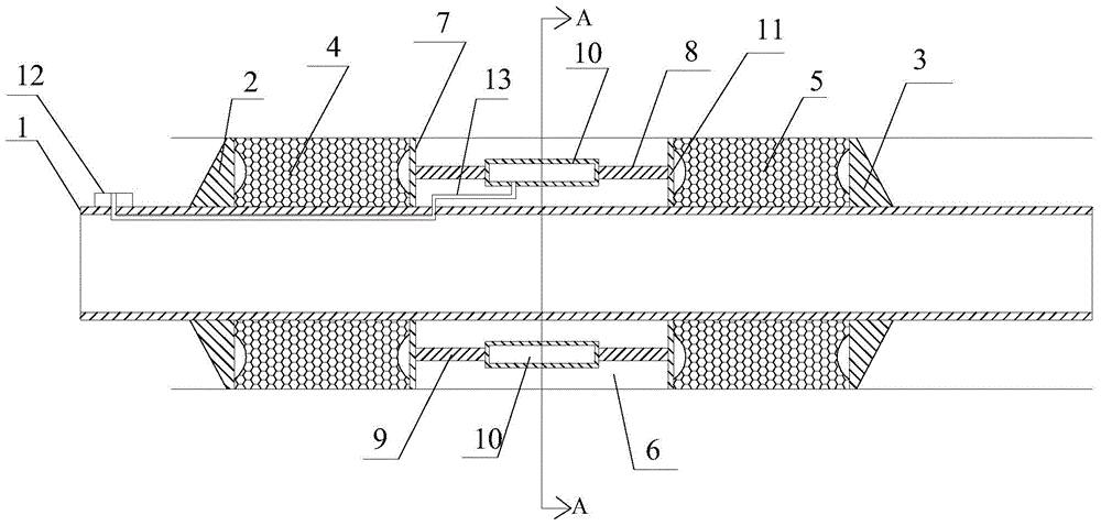
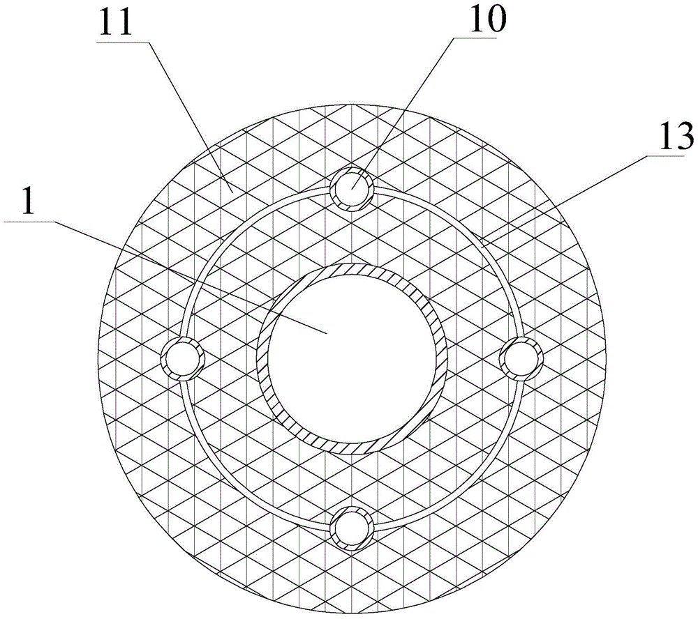
[0015] The invention provides a gas drainage and sealing device, such as figure 1 and figure 2 As shown, it includes a gas drainage pipe 1, wherein the gas drainage pipe 1 is provided with a first fixed rigid baffle 2 and a second fixed rigid baffle 3, and one side of the first fixed rigid baffle 2 is provided with a second A solid rubber body 4, a second solid rubber body 5 is arranged on one side of the second fixed rigid baffle plate 3, and the outer periphery of the gas drainage pipe 1 between the first solid rubber body 4 and the second solid rubber body 5 forms a housing The c...


PUM


Abstract

The invention discloses a gas drainage and sealing device, which includes a gas drainage pipe, wherein the gas drainage pipe is provided with a first fixed rigid baffle and a second fixed rigid baffle, and the first fixed rigid baffle is a A first solid rubber body is arranged on one side of the second fixed rigid baffle, and a second solid rubber body is arranged on one side of the second fixed rigid baffle, and the outer circumference of the gas drainage pipe between the first solid rubber body and the second solid rubber body forms a receiving cavity A telescopic mechanism for deforming the first solid rubber body and the second solid rubber body is arranged in the accommodating cavity. Squeeze the first solid rubber body and the second solid rubber body of the gas drainage and sealing device through the telescopic mechanism, so that the radial deformation of the solid rubber body increases to achieve the sealing effect and reduce the cost of sealing and gas drainage; The hole sealing device is easy to operate and has remarkable effects, which can prevent external air from entering the extraction borehole, effectively reduce the cost of hole sealing, and improve the quality and efficiency of the two-time sealing of the hole.

Description

technical field [0001] The invention relates to a gas drainage and sealing device. Background technique [0002] Mine gas seriously threatens the safe production of coal mines, and gas disasters cause many casualties and huge property losses every year. The state requires that high-gas mines must be pumped before mining for the control of coal mine gas, and gas drainage is a permanent measure. my country's coal mine gas extraction rate is generally low. In addition to the influence of geological conditions such as poor coal seam permeability, the main reason is that the quality of the hole sealing of the borehole is poor, and the gap around the borehole cannot be effectively sealed. The gas concentration decays quickly and the gas flow rate is low. [0003] At present, domestic drilling and sealing methods include the following: polyurethane sealing, mechanical elastic sealing, inflatable sealing, hydraulic expansion sealing, new pressurized grouting sealing, etc. It is di...

Claims


Application Information

Patent Timeline
Patent Type & Authority Patents(China)
IPC IPC(8): E21B33/128
Inventor 于海峰程国强于桂萍朱洪利赵芳姚壮壮尚永会孙业强
Owner SHANDONG UNIV OF SCI & TECH
Why Eureka
Try Eureka