
Stope structure arrangement mode suitable for underground mine high productivity and low cost subsequent filling

A technology with structural arrangement and high production capacity, which is applied in underground mining, ground mining, earth square drilling and mining, etc., can solve the problems that hinder underground mines from increasing production capacity, complicated process, and increased cost, so as to reduce the amount of tailings, simplify the process, and reduce the The effect of filling costs

Active Publication Date: 2012-12-12
SINOSTEEL MAANSHAN INST OF MINING RES
View PDF6 Cites 7 Cited by
  • Summary
  • Abstract
  • Description
  • Claims
  • Application Information

AI Technical Summary

Problems solved by technology

[0003] At present, the mining method of open-pit mining followed by filling has been tested in China, and remarkable achievements have been made, mainly including the method of open-pit mining followed by filling in the downward large hole stage, the method of segmented open-pit mining followed by filling mining, and the method of mine mining followed by filling mining. methods, etc., but there are still limitations on production capacity and production cost. The main reason is that the stope adopts two-step mining. After the first-step mining, it is necessary to use high-strength tailings to cement the goaf to create conditions for the second-step mining. This results in increased cost and complicated process, which hinders the further increase of production capacity of underground mines

Method used


Image

  • Stope structure arrangement mode suitable for underground mine high productivity and low cost subsequent filling
  • Stope structure arrangement mode suitable for underground mine high productivity and low cost subsequent filling

Examples


Embodiment Construction

[0025] In order to further describe the present invention, a stope structural arrangement suitable for large production capacity and low-cost subsequent filling of underground mines according to the present invention will be described in detail below in conjunction with the accompanying drawings and embodiments.

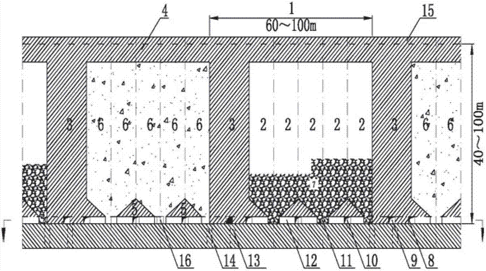
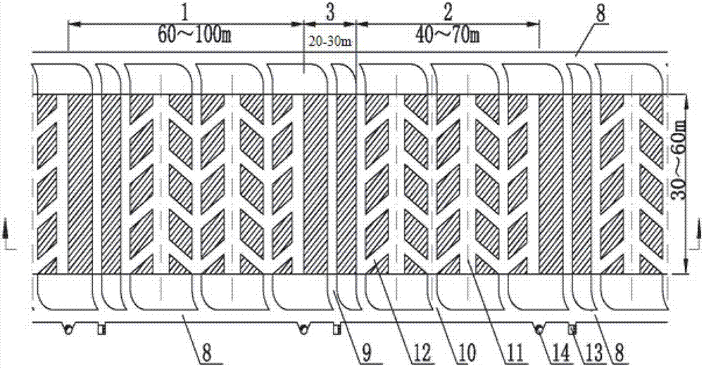
[0026] Depend on figure 1 The shown principle and layout longitudinal projection diagram of a stope structure layout mode suitable for large production capacity and low-cost subsequent filling of underground mines according to the present invention figure 2 The principle and bottom structure layout diagram of a stope structure layout suitable for large production capacity and low-cost subsequent filling of the present invention shown in the present invention shows that the present invention divides the combination of underground thick and large ore sections into multiple mining panels 1. Each panel area is divided into 3~6 continuous stopes 2. A panel interval colum...


PUM


Abstract

The invention discloses a stope structure arrangement mode suitable for underground mine high productivity and low cost subsequent filling. Underground ore block is divided into panels (1), the interior of each panel (1) is divided into 3-6 continuous stopes (2) and a panel stud (3), a panel crown pillar (4) and a panel sill pillar (5) are arranged in a vertical direction, ores (7) in the stopes (2) drop into a stope trenches (11) through blasting, a carry-scraper passes through an ore removal roadway (10), ore loading is performed in ore removal access road (12), ores are transported to drift roadway (8) and are discharged into an orepass (14). After the stope ore removal, tailings pass through a filling roadway (15) and are subjected to pipeline filling to a dead zone to form a panel filling body (6). After the filling of the panel stopes (2) is finished, adjacent panel stopes (2) are stoped, and subsequently the formed dead zones are filled. After the filling of the adjacent panel stopes (2) is fihished, a part of the panel studs (3) is recovered, dead zone formed by the panel studs are filled, and finally the dead zones are eliminated. The stope structure arrangement mode has the advantages that the mining intensity can be improved by utilizing limited ore body distribution area, the production capacity is increased, and mining production and dead zone filling treatment costs are reduced.

Description

technical field [0001] The invention relates to an underground mine mining method, in particular to a stope structure arrangement suitable for a subsequent filling mining method suitable for high-efficiency mining of large-scale underground mines. It is suitable for non-coal underground mines to use limited ore body distribution area to increase mining intensity, expand production capacity, and reduce mining production and empty area filling processing costs. Background technique [0002] There are three basic methods of underground mining in metal mines: one is the open field method, the other is the caving method, and the third is the filling method. Various mining methods have their own conditions of use: open-field mining method has large production capacity, low mining cost, and poor safety; filling mining method has low production capacity and high production cost, and is often used to mine high-value ores; caving mining method has high production capacity, However, t...

Claims


Application Information

Patent Timeline
Patent Type & Authority Applications(China)
IPC IPC(8): E21C41/16
Inventor 胡永泉张传信赵继银喻六平张鹏刘培正
Owner SINOSTEEL MAANSHAN INST OF MINING RES
Learn More