Speed reducer structure

A technology of reducer and output shaft, applied in the field of structure and structure of reducer, can solve problems such as damage to mechanical equipment parts

Inactive Publication Date: 2012-12-12
姜秀新
View PDF0 Cites 4 Cited by
  • Summary
  • Abstract
  • Description
  • Claims
  • Application Information

AI Technical Summary

Problems solved by technology

[0003] The purpose of the present invention is to provide a structure of a reducer, which overcomes the defect that the existing reducer has no torque limiting function, and it is easy to cause damage to mechanical equipment parts after overloading

Method used


Image

  • Speed reducer structure

Examples


Embodiment Construction

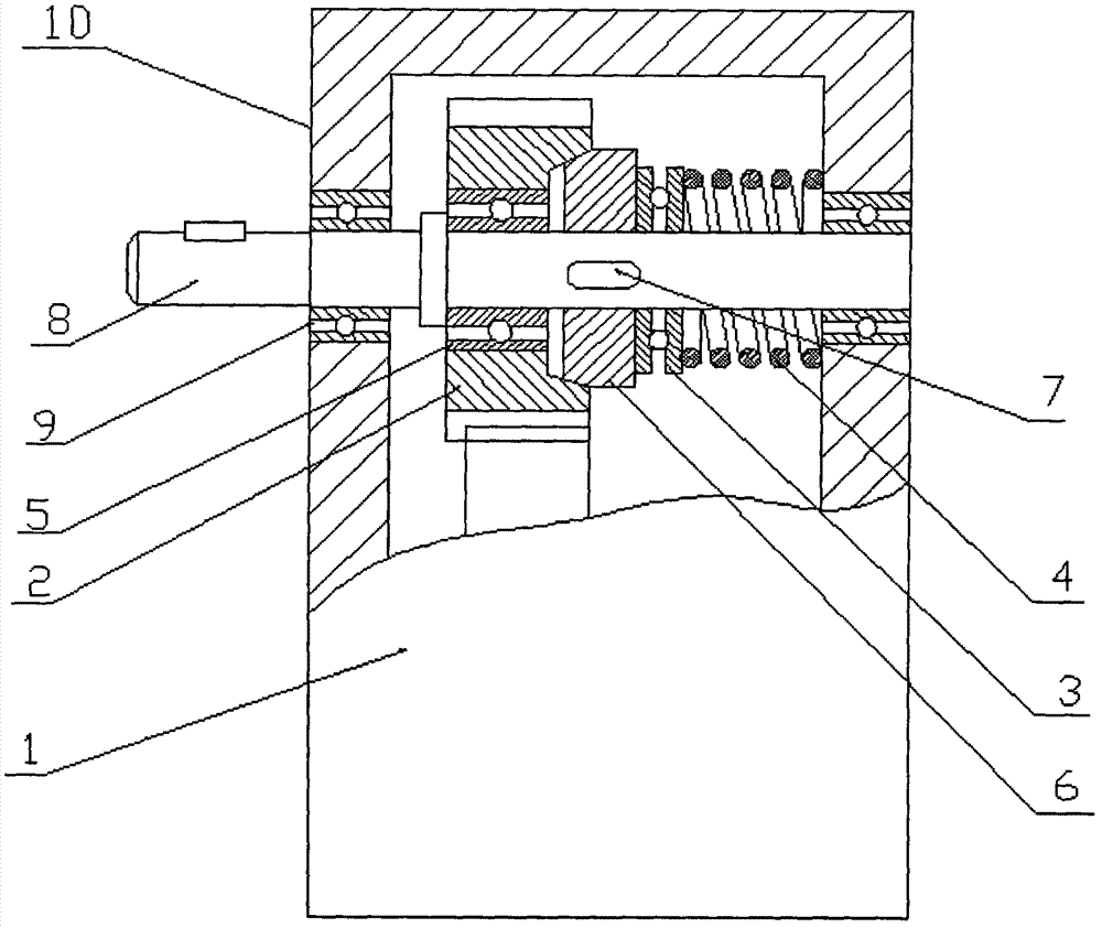
[0009] Install the final gear 2 on the output shaft 8 through the ordinary bearing 5, and the friction disc 6 is installed on the output shaft 8 on the side of the final gear 2 through the key 7, and on the side of the final gear 2 corresponding to the friction disc 6 There is an inner tapered surface with the same taper as the end surface of the friction disc 6. The plane bearing 3 is installed on the top of the output shaft 8 and is close to the right side of the friction disc 6. The output shaft between the plane bearing 3 and the inner surface of the gearbox 1 8 is installed with a spring 4, the spring 4 passes through the plane bearing 3, and the friction disc 6 and the final gear 2 are installed on the output shaft 8 through the tapered surface of each body, and then the output shaft 8 is installed on the gearbox through the output shaft bearing 9 1 above.


PUM


Abstract

Disclosed is a speed reducer structure. A last stage gear is installed on an output shaft through an ordinary bearing, a friction disk is installed on the output shaft on one side of the last stage gear through a key, an inner tapered surface which has same conical degrees with an end surface of the friction disk is arranged on one surface of the last stage gear, the surface of the last stage gear corresponds to the friction disk, a plane bearing is installed on the output shaft and leans against the right side of the friction disk, a spring is installed on the output shaft between the plane bearing and an inner side surface of a gear box, the spring penetrates through the plane bearing, the friction disk and the last stage gear are installed on the output shaft through conical surfaces of the friction disk and the last stage gear, and the output shaft is installed on the gear box through output shaft bearings.

Description

technical field [0001] The invention relates to a structure, in particular to a structure of a speed reducer, which belongs to the technical field of mechanical transmission. Background technique [0002] The reducer is an important transmission part in mechanical transmission. At present, in the reducer products, the reducer is only used as a power transmission part. Since there is no torque limiting function, mechanical parts are often damaged after overloading. Accidents happen. Contents of the invention [0003] The purpose of the present invention is to provide a structure of a speed reducer, which overcomes the defect that the existing speed reducer has no torque limiting function, and the parts of the mechanical equipment are easily damaged after being overloaded. [0004] The technical solution adopted by the present invention to achieve the above purpose is: a structure of a reducer, which is to install the final gear on the output shaft through a common bearing,...

Claims


Application Information

Patent Timeline
Patent Type & Authority Applications(China)
IPC IPC(8): F16H35/10F16H57/023F16D43/21
Inventor 姜秀新
Owner 姜秀新
Why Eureka
Try Eureka