Image generation apparatus and image generation method

An image generation device and image generation technology are applied in image communication, optical observation device, transportation and packaging, etc., and can solve problems such as user misuse

Active Publication Date: 2012-12-12
FUJITSU GENERAL LTD
View PDF6 Cites 12 Cited by
  • Summary
  • Abstract
  • Description
  • Claims
  • Application Information

AI Technical Summary

Problems solved by technology

However, if the front image is displayed when the vehicle is traveling in the rear direction, there is a possibility that the user may mistakenly think that the vehicle is traveling in the front direction.

Method used


Image

  • Image generation apparatus and image generation method
  • Image generation apparatus and image generation method
  • Image generation apparatus and image generation method

Examples


no. 1 Embodiment approach

[0074]

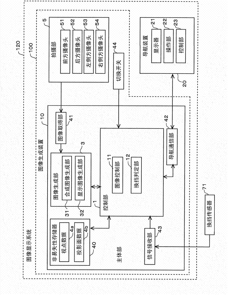
[0075] figure 1 It is a figure which shows the structure of the image display system 120 of 1st Embodiment. This image display system 120 is used in a vehicle (an automobile in the present embodiment), and has a function of displaying an image showing an area around the vehicle in the vehicle interior. A user of the image display system 120 (typically, a driver) can grasp the surrounding conditions of the vehicle in almost real time by using the image display system 120 .

[0076] Such as figure 1 As shown, the image display system 120 mainly includes an image generating device 100 that generates an image showing the surrounding area of ​​the vehicle, and a navigation device 20 that displays various information to a user seated in the vehicle. The image generated by the image generating device 100 is displayed on the navigation device 20 .

[0077] The main function of the navigation device 20 is to guide a route to a destination. The navigation device 20 includ...

no. 2 Embodiment approach

[0151] Next, a second embodiment will be described. The operation and processing of the image display system of the second embodiment are substantially the same as those of the first embodiment, so the following description will focus on differences from the first embodiment. In the first embodiment, when the traveling direction of the vehicle 9 is backward (that is, in the rear mode M3), a display image including a rear image is displayed, and a display image including a front image is not displayed.

[0152] On the other hand, in the second embodiment, when the traveling direction of the vehicle 9 is backward, the display image including the rear image and the display image including the front image can be switched and displayed by the user's operation. More specifically, when the traveling direction of the vehicle 9 is backward, the image generator 3 selectively generates one of a display image including a rear image and a display image including a front image according to ...

no. 3 Embodiment approach

[0166] Next, a third embodiment will be described. The operation and processing of the image display system of the third embodiment are substantially the same as those of the first embodiment, so the following description will focus on differences from the first embodiment.

[0167] In the conventional image display system, the case where the side mirrors of the vehicle are housed is not considered. The side mirror of the vehicle is stored when the side of the vehicle is close to other objects when the vehicle meets other vehicles, etc., or when the vehicle is driving on a relatively narrow road, other than when the vehicle is parked a lot of. Therefore, when the side mirrors are housed in a state where the vehicle can run, it is presumed that the side surface of the vehicle 9 is close to another object. Therefore, in the image display system 120 of the third embodiment, when the side mirror 93 is housed, a useful display image is displayed when the vehicle 9 is traveling in...


PUM


Abstract

The invention provides an image generation apparatus and an image generation method through which a user can notice the object backward that exists in the direction opposite to the traveling direction of the vehicle. Therefore in the image display system, a shift determining part determines the traveling direction of a vehicle (9). The composite image CP1 which is generated by a composite image generator shows a peripheral area (A1) as the periphery of the vehicle (9) and a backward area (A2) as the area behind the vehicle (9) and includes the peripheral area (A1) that centers the image of the vehicle (9) and is viewed from a virtual viewpoint that looks down the vehicle (9). A display displays a display image (DP1) which includes the composite image (CP1). The display image (DP1) includes the composite (CP1) which shows the backward area (A2) which is opposite to the traveling direction of the vehicle (9). The user can notice the object backward that exists in the direction opposite to the traveling direction of the vehicle (9) by looking at the composite image (CP1).

Description

technical field [0001] The present invention relates to a technique for displaying images in a vehicle. Background technique [0002] Conventionally, an image display system for displaying an image showing a surrounding area of ​​a vehicle on a monitor in a vehicle interior based on an image captured by a camera mounted on a vehicle such as an automobile is known. By using this image display system, the user (typically, the driver) can grasp the situation around the vehicle in almost real time. [0003] For example, if the image display system that displays a rear image showing the rear of the vehicle is used when the vehicle is backing up, the user can easily grasp objects that exist behind the vehicle. Therefore, the user can safely reverse the vehicle while avoiding contact of the vehicle with the object. [0004] In addition, in recent years, an image display system that displays a bird's-eye view image observed from a virtual point of view overlooking the vehicle base...

Claims


Application Information

Patent Timeline
Patent Type & Authority Applications(China)
IPC IPC(8): H04N7/18H04N5/265B60R1/00
CPCB60R2300/303B60R1/00B60R2300/607H04N7/181B60R2300/605
Inventor 清幸荣泽田康嘉春本哲山下善嗣
Owner FUJITSU GENERAL LTD
Why Eureka
Try Eureka