Locking hole of inner fixing frame

A technology of locking holes and fixing frames, applied in the field of locking holes

Inactive Publication Date: 2012-12-19
山东省文登市整骨科技开发有限公司
View PDF6 Cites 0 Cited by
  • Summary
  • Abstract
  • Description
  • Claims
  • Application Information

AI Technical Summary

Problems solved by technology

[0002] For a long time, most fractures and bone orthopedics have adopted bone plate technology. The contact and fixation between the bone plate and the bone is based on mutual friction, so the holes of the bone plate only have the function of pressurizing and tensioning the bone in close contact.
The internal fixator is different from the bone plate. There is a certain gap between the main bod

Method used


Image

  • Locking hole of inner fixing frame
  • Locking hole of inner fixing frame
  • Locking hole of inner fixing frame

Examples


Embodiment 1

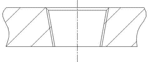
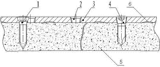
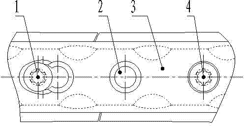
[0012] Embodiment 1, a locking hole of an internal fixator, refer to figure 1 , figure 2 , image 3 As shown, the hole is a tapered threaded through hole, and is evenly distributed on the internal fixator with a gap of 0.3mm-0.5mm between the bone and the bone; through the locking hole slot, the end of the locking screw 4 enters the bone 5, and the locking hole 2, The locking screw 4, the internal fixation frame 3 and the bone 5 form a non-contact fixed frame system.

[0013] During use, through the locking hole, the end of the locking screw uses the locking screw to fix the internal fixator on the fracture site. With the cooperation of the compression bone screw 1, the internal fixator is kept at a distance of 0.3mm- With a distance of 0.5mm, it suspends itself on the bone surface to form a non-contact fixed frame, so that the periosteum will neither be peeled off nor be compressed and necrotic, so as to maintain good blood supply at the fracture end and promote fracture h...


PUM


Abstract

The invention provides a locking hole of an inner fixing frame, which is characterized in that the hole is a tapered thread through hole and is uniformly distributed on the inner fixing frame which has a distance of 0.3-0.5 mm from a bone.

Description

technical field [0001] The invention relates to a locking hole in an orthopedic internal fixation system. Background technique [0002] For a long time, most fractures and bone orthopedics have adopted bone plate technology. The contact and fixation between the bone plate and the bone is based on mutual friction. Therefore, the holes of the bone plate only have the function of pressurizing and tensioning the bone in close contact. The internal fixator is different from the bone plate. There is a certain gap between the main body of the fixator and the bone. This gap is for not destroying the periosteum and maintaining the blood supply of the fracture end, accelerating fracture healing and improving the quality of fracture healing. Therefore, internal fixation The main body of the frame and the screw must be locked, and it must be very stable. At present, there is no report about the locking hole of the internal fixation frame. Contents of the invention [0003] In order t...

Claims


Application Information

Patent Timeline
IPC IPC(8): A61B17/80
Inventor 张恩忠
Owner 山东省文登市整骨科技开发有限公司
Why Eureka
Try Eureka