Aortic Stent Graft with Chimney Stent Support Tube

A stent support and stent-graft technology, which is applied in the field of medical devices, can solve the problems of blood flow channel occlusion, aortic stent-grafts not firmly adhered to the wall, and the cross-section of the blood flow channel becomes smaller, so as to avoid endoleak and blood flow. The effect of reducing the cross section of the flow channel

Inactive Publication Date: 2016-04-06
THE THIRD AFFILIATED HOSPITAL OF THIRD MILITARY MEDICAL UNIV OF PLA
View PDF12 Cites 0 Cited by
  • Summary
  • Abstract
  • Description
  • Claims
  • Application Information

AI Technical Summary

Problems solved by technology

However, there are two disadvantages in this structure at present: 1) the chimney stent is located between the aortic stent graft and the inner wall of the aorta, which causes the aortic stent graft to be not firmly attached to the wall, resulting in endoleaks; 2) due to the aortic stent graft The elastic tension of the stent is stronger than that of the chimney stent. Long-term compression of the chimney stent will cause the cross-section of the blood flow channel formed by the chimney stent to become smaller or blocked, which will affect the blood circulation of important branch vessels and lead to ischemia in relevant parts of the body.

Method used


Image

  • Aortic Stent Graft with Chimney Stent Support Tube

Examples


Embodiment Construction

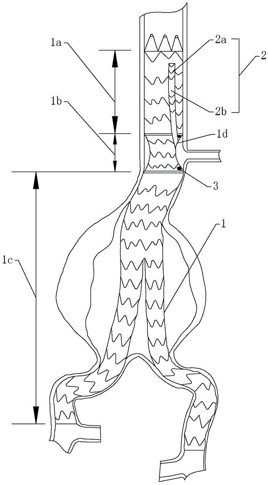
[0015] The present invention will be described in detail below in conjunction with the accompanying drawings, as shown in the figure: the aortic stent graft with chimney stent support pipe includes a main stent 1, and at least one support for releasing the chimney stent is arranged in the main stent Pipeline 2, the support pipe 2 is set close to the front end of the main bracket 1, and there are marks 3 around the proximal end of the support pipe 2, which are used for the guide wire to pass when the chimney support is released. The support pipe 2 is tightly and fixedly connected with the inner wall of the main support 1, and the main support wall is provided with a through hole 1d communicating with the support pipe, and marks 3 are also provided around the through hole 1d, and the main support is composed of a metal skeleton and covered with a metal The composition of the stent graft outside the skeleton. During the operation, CT angiography and other imaging examinations are ...


PUM


Abstract

The invention discloses an aorta covered stent with a chimney stent supporting pipe. The aorta covered stent comprises a main stent, at least one supporting pipe for releasing a chimney stent is arranged in the main stent, arranged close to the front end of the main stent and tightly and fixedly connected with the inner wall of the main stent, and the wall of the main stent is provided with a through hole communicated with the supporting pipe. By means of the aorta covered stent of the structure, the at least one supporting pipe is reserved in the aorta covered stent, after the aorta covered stent is released and attached to the wall, the chimney stent is then released by the reserved supporting pipe into important branch blood vessels, and blood flow supplying to the important branch blood vessels is accordingly guaranteed. Due to the fact that the chimney stent is released to the inner side of the aorta covered stent, wall attaching of the aorta covered stent cannot be influenced, and inner leakage can be accordingly and effectively avoided; in addition, the aorta covered stent cannot press the chimney stent, and decreasing of cross sections of blood flow channels or blocking of the blood flow channels formed by the chimney stent can be effectively avoided.

Description

technical field [0001] The invention relates to the field of medical instruments, in particular to an aortic covered stent with a chimney stent supporting pipe. Background technique [0002] In the present invention, the term "distal end" refers to the end away from the heart along the blood flow direction, and "proximal end" refers to the end close to the heart along the blood flow direction. [0003] With the development of interventional technology, more and more stents are used. Problems that could only be solved by traditional surgical techniques or hybrid techniques, such as dissecting aneurysms at the aortic arch and abdominal aortic aneurysms at the visceral artery, can now be released Aortic stent graft, so as to achieve the purpose of treatment. At present, in order to isolate the breach while not affecting the blood supply of important branch vessels, one or more chimney stents are usually released between the aortic stent graft and the inner wall of the aorta to...

Claims


Application Information

Patent Timeline
Patent Type & Authority Patents(China)
IPC IPC(8): A61F2/07
Inventor 文亚渊陈懿李新颖李志荣
Owner THE THIRD AFFILIATED HOSPITAL OF THIRD MILITARY MEDICAL UNIV OF PLA
Why Eureka
Try Eureka