
Unattended remote monitoring control system for road junction of railways

A technology of remote monitoring and control system, applied in the field of remote monitoring and control system for unattended railway crossings, can solve the problems of not being able to respond immediately, not being able to achieve real-time and accurate intelligent control, etc., achieving significant social and economic benefits, Precise automatic control and strong environmental adaptability

Active Publication Date: 2012-12-19
TONGJI UNIV
View PDF6 Cites 68 Cited by
  • Summary
  • Abstract
  • Description
  • Claims
  • Application Information

AI Technical Summary

Benefits of technology

The technical effect of this new technology described by this patented innovation includes accurate automated control that prevents people or objects on footage entering an intersection without being detected during normal traffic flowing around them (which could lead to accidents). This ensures safety while also providing effective security measures against potential threats such as fires or other disasters. Additionally, there are various ways to detect if any unusual events occur within certain time frames based on factors like weather patterns or road usage levels. Overall, these improvements improve overall efficiency and reliability across railways.

Problems solved by technology

The technical problem addressed in this patented text relates to improving safety measures during train operation at high speeds without causing collateral damage or injury due to poor visibility caused by traditional systems that require manual monitoring and adjustment over time.

Method used


Image

  • Unattended remote monitoring control system for road junction of railways

Examples


Embodiment

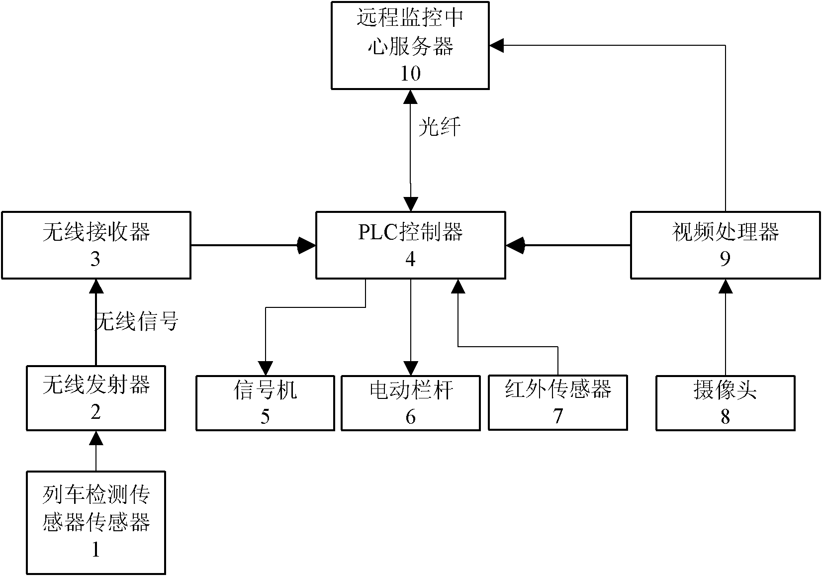
[0018] Such as figure 1 As shown, an unattended railway crossing remote monitoring and control system is set at the intersection of railways and highways. The remote monitoring and control system includes wireless sensors, crossing control boxes, cameras 8, signal machines 5, electric railings 6, infrared sensors 7. Remote monitoring center server 10: The remote monitoring center server 10 can display the crossing monitoring screen in real time; give an alarm to the abnormal situation of the crossing; make a remote voice announcement; remotely control the electric railing of the crossing. The wireless sensor is set on the side of the railway 1.2km away from the road. The wireless sensor includes a train detection sensor 1 and a wireless transmitter 2. The train detection sensor 1 is a passive magnetoelectric sensor, and the wireless transmitter 2 is powered by solar energy. Crossing control box includes wireless receiver 3, PLC controller 4, video processor 9: PLC controller 4...


PUM


Abstract

The invention relates to an unattended remote monitoring control system for a road junction of railways, which is arranged at the intersection of a railway and a road. The remote monitoring control system comprises a wireless sensor, a road junction control box, a camera, a signaler, an electric barrier, an infrared sensor and a remote monitoring central server; the wireless sensor is in wireless connection with the road junction control box; the infrared sensor is arranged at both sides of the electric barrier and is connected with the road junction control box; the camera, the signaler and the electric barrier are respectively connected with the road junction control box; and the road junction control box is connected with the remote monitoring central server. Compared with the prior art, the system is based on the global energy saving of an urban track traffic system and all operating conditions of a vehicle and has the advantages of increasing the utility ratio of a vehicular energy-storage system and realizing the maximization energy saving of a track traffic system.

Description


Claims


Application Information

Patent Timeline
Owner TONGJI UNIV
Learn More