Sealing device used for chemical reactor

A technology of chemical reactors and sealing devices, which is applied to the sealing of engines, chemical instruments and methods, chemical/physical processes, etc., and can solve problems such as damage, hardship, and time-consuming

Inactive Publication Date: 2012-12-19
AMMONIA CASALE SA
View PDF3 Cites 0 Cited by
  • Summary
  • Abstract
  • Description
  • Claims
  • Application Information

AI Technical Summary

Problems solved by technology

However, the disadvantage of this technique is that the gland packing type gasket is installed in a completely manual manner, which is time consuming and laborious, in practice carried out on the job site and requires direct access by the operator
and has also been observed to have the drawback of gradual failure of gland packing type gaskets

Method used


Image

  • Sealing device used for chemical reactor
  • Sealing device used for chemical reactor
  • Sealing device used for chemical reactor

Examples


Embodiment Construction

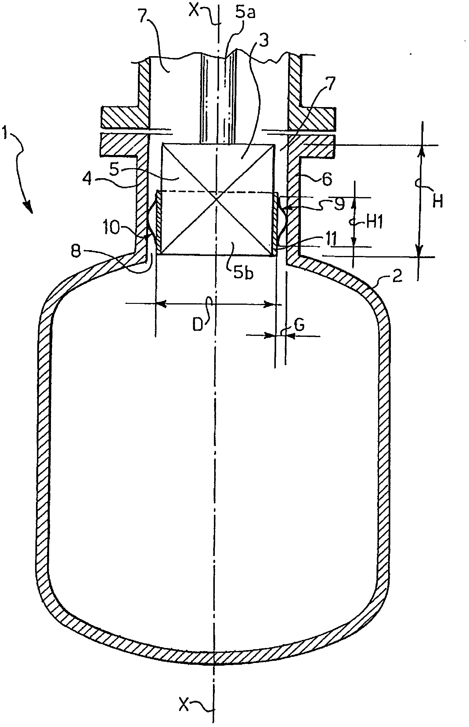
[0016] Referring to the accompanying drawings, the chemical reactor is generally indicated by reference numeral 1 . The chemical reactor 1 includes a casing 2 and a male member 3 inserted into a female member 4 with a gap. In particular in the combustion or oxidation reactor 1 the convex member 3 is the burner 5, which has an elongated cylindrical shape with axis X-X and is supported at its end 5a by the casing, and which has an opposite cantilevered end 5b, the cantilever The end 5 b is inserted coaxially and with play into the female part 4 , which is a housing 6 which defines an opening 7 in the housing 2 .

[0017] An annular gap 8 is formed between the outer surface 3 a of the male part 3 and the inner surface 4 a of the female part 4 . The protrusion 3 has a larger cross-sectional dimension ranging from 300 to 1500 mm. In this example, the diameter of the male element 3 is approximately 600 mm. The gap 8 also has larger dimensions, in the order of 1-2 cm. In this exa...


PUM


Abstract

A sealing device used for chemical reactors (1 and 20) is safe, reliable, and simple in structure, and easy to assemble and disassemble, wherein the chemical reactors (1 and 20) comprise shells (2) and convex pieces (3) and metal sheets (10), the convex pieces are supported by the shells (2) and inserted into convex strips (4) by certain intervals, and the metal sheets (10) can be fixedly connected on the convex pieces (3) in a deformation manner and protrude in a gap (8) to be used for blocking a fluid channel of the gap.

Description

technical field [0001] The present invention relates to a chemical reactor of the type comprising a housing, a male part supported by the housing and having a male part inserted with clearance into a female part connected to the housing, and a means for preventing the passage of the male part and the female part The sealing device for the fluid passage between the gaps. Background technique [0002] Chemical reactors of the particular type mentioned above generally have large dimensions, and when manufacturing the various elements that make up the reactor, too strict machining tolerances cannot be imposed, since this would result in unreasonably high manufacturing costs. In fact, the various elements have rather coarse tolerances in all respects, especially with regard to their dimensions, coaxiality, concentricity and surface finish. In fact, this structure belongs to the category of carpentry workshops and boiler workshops whose structural requirements are completely diff...

Claims


Application Information

Patent Timeline
IPC IPC(8): F16J15/08B01J19/00
Inventor 恩里科・里奇
Owner AMMONIA CASALE SA
Why Eureka
Try Eureka