Heat exchange unit for isothermal chemical reactors

a technology of isothermal chemical reactors and heat exchange units, which is applied in indirect heat exchangers, lighting and heating apparatuses, laminated elements, etc., can solve the problems of reducing heat exchange efficiency, difficult to direct the flow of operating fluid in the interior of the heat exchanger in the designated direction, and a plate-shaped heat exchanger

Inactive Publication Date: 2005-03-24
CASALE SA
View PDF10 Cites 41 Cited by
  • Summary
  • Abstract
  • Description
  • Claims
  • Application Information

AI Technical Summary

Benefits of technology

[0010] This problem is solved according to the invention by a heat exchange unit for isothermal radial or axial-radial chemical reactors, with an overall configuration which is substantially annular and cylindrical having a passage with a predetermined diameter running through it axially, characterized in that it comprises a plurality of substantially rectangular, flattened box-shaped heat exchangers, distributed in many coaxial and concentric arrays, defining in said unit a plurality of radial alignments with a substantially radial arrangement, and wherein said exchangers have long sides paralle...

Problems solved by technology

As much as they are advantageous under different points of view, as for example that of the large surface made available for the heat exchange, the plate-shaped heat exchangers of the aforementioned type suffer from a technical drawback consisting of the difficulty in directing the flow of operating fl...

Method used


Image

  • Heat exchange unit for isothermal chemical reactors
  • Heat exchange unit for isothermal chemical reactors
  • Heat exchange unit for isothermal chemical reactors

Examples


Embodiment Construction

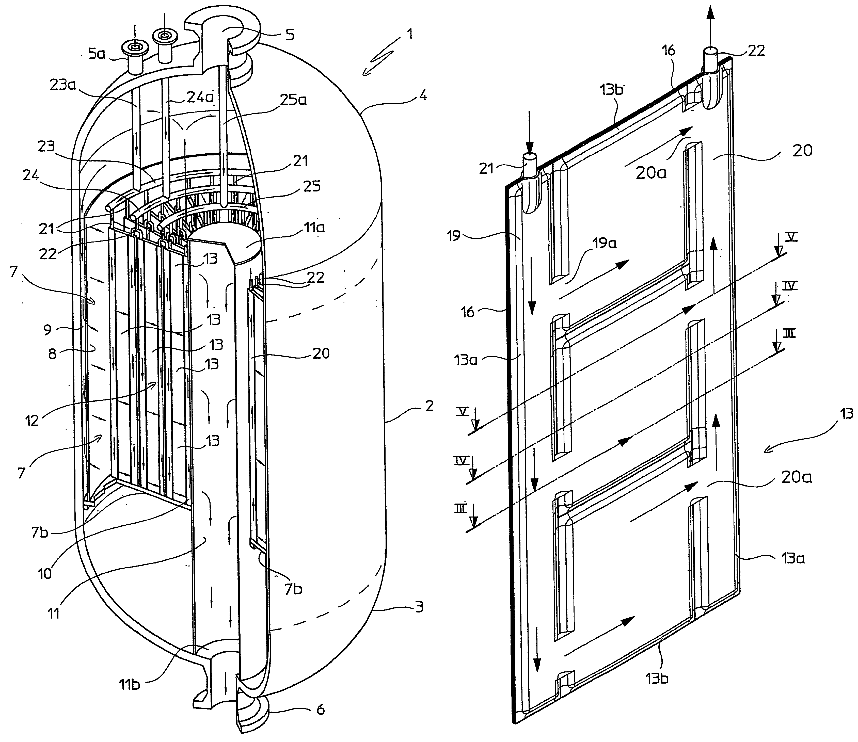
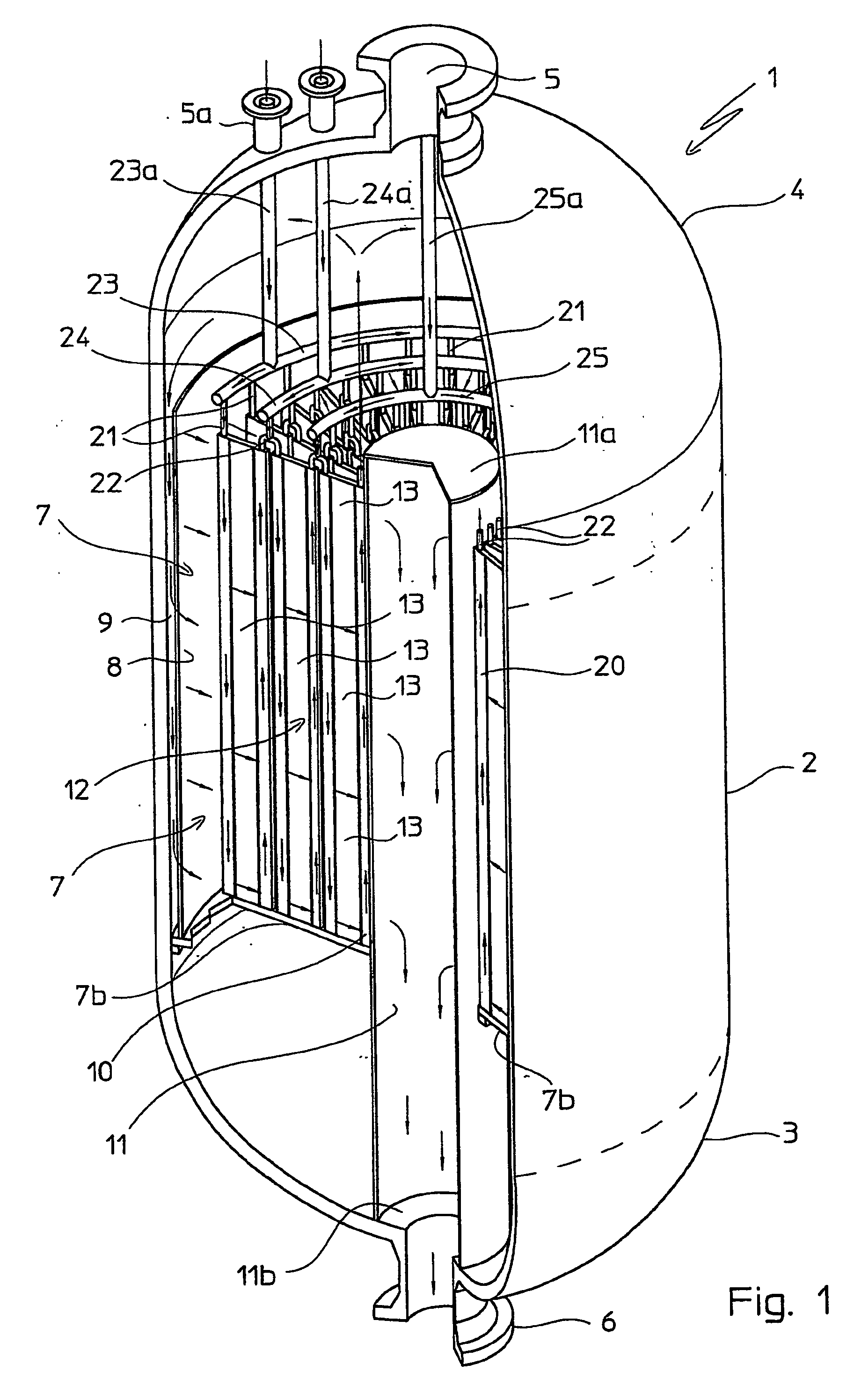
[0019] With reference to FIG. 1, with 1 is wholly indicated an isothermal reactor comprising a cylindrical shell 2, with a vertical axis, closed at the opposite ends with respective bottoms, lower 3 and upper 4, conventionally equipped with passages 5, 6 for the introduction and the discharge of the reactant gases and of the gaseous reaction products into and from said isothermal reactor 1, respectively, as will become clearer from the rest of the description.

[0020] In the shell 2 is defined a reaction zone, in which is conventionally supported a catalytic basket 7, with a substantially cylindrical configuration, having an annular transversal section. Said basket 7 substantially consists of an outer cylindrical wall 8, which, together with said shell 2, defines a space 9 with a reduced width, an inner cylindrical wall 10 and an annular bottom of the conventional type outlined in 7b.

[0021] The inner wall 10 centrally defines an axial passage, in which is generally supported a pipe ...


PUM


Abstract

A heat exchange unit for isothermal radial or axial-radial chemical reactors (1), with an overall configuration which is substantially annular and cylindrical having a passage (11) with a predetermined diameter running through it axially, is distinguished in that it comprises a plurality of substantially rectangular, flattened box-shaped heat exchangers (13), distributed in many coaxial and concentric arrays, defining in the unit (12) a plurality of radial alignments with a substantially radial arrangement, and wherein the exchangers (13) have long sides (13a) parallel to the axis of the unit (12) and short sides (13b) extending radially, each of the exchangers (13) comprising an inner chamber (17), intended to be passed through by an operating heat exchange fluid, at least one distributor pipe (19) and at least one collector pipe (20) of the operating fluid, associated with two respective opposing sides (13a) of the exchanger (13) and extending along them, the pipes (19, 20) being in fluid communication, on the one side, with the chamber (17) through at least one opening (19a, 20a) formed therein and, on the other side, with the outside of the exchanger (13), through respective inlet and outlet fittings (21, 22) for the operating fluid.

Description

FIELD OF APPLICATION [0001] The present invention relates, in its broader aspect, to a chemical reactor of the type comprising a substantially cylindrical shell (or pressure vessel) closed at its opposite ends by respective bottoms, a reaction zone in said shell wherein at least a catalytic bed is placed, and a heat exchange unit embedded in said catalytic bed. [0002] Such a reactor is particularly useful for carrying out exothermic and endothermic reactions occurring in substantially isothermal conditions, i.e. conditions in which the reaction temperature is controlled in a rather limited range of values around a predetermined value. [0003] In the following description and claims, a reactor of the aforementioned type is referred to as pseudoisothermal or, in short, isothermal reactor. [0004] More in detail, the present invention relates to an isothermal reactor of the type being considered, structured internally to allow the reactant gases and the gaseous reaction products to cross...

Claims


Application Information

Patent Timeline
IPC IPC(8): B01J8/02B01J19/24F28D9/00F28F3/14
CPCB01J8/0214B01J8/0285B01J19/249F28F9/0275F28D9/0006F28D9/0031B01J2208/022F28F2250/102
Inventor FILIPPI, ERMANNORIZZI, ENRICOTAROZZO, MIRCO
Owner CASALE SA
Why Eureka
Try Eureka