[0027] Example 1
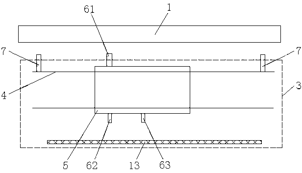
[0028] Such as figure 2 As shown, a non-contact online roll profile measurement device includes a reference surface 13, a measurement platform 3, a slide rail 4, a slide 5, a first slide probe 61, a second slide probe 62, and a third slide. The block probe 63 and the slide rail probe 7, the reference surface 13 and the slide rail 4 are set on the measurement platform 3, the slide block 5 is set on the slide rail 4, and there are two slide rail probes 7 which are respectively set near the roll At both ends of the slide rail 4 on the side of 1, the first slider probe 61 is set on the side of the slider 5 close to the roll 1, and the second slider probe 62 and the third slider probe 63 are set far from the slider 5 Two ends of one side of the roll 1; the axis of the slide rail 4 is parallel to the reference plane 13, the reference plane 13 is parallel to the axis of the roll 1, the reference plane 13 is perpendicular to the measuring platform 3, and the axis of the slide rail 4 is parallel to the axis of the roll 1; The extended surface of the measuring platform 3 is in the same plane as the axis of the roll 1, and the axes of the first slider probe 61, the second slider probe 62, the third slider probe 63 and the slide rail probe 7 are in the same plane as the axis of the measuring platform 3 In the same plane, the first slider probe 61 and the second slider probe 62 are coaxial, the axes of the first slider probe 61, the second slider probe 62 and the third slider probe 63 are parallel, and the axis of the slide rail probe 7 It is perpendicular to the axis of the slide rail 4. The slider 5 moves on the slide rail 4, and the measurement value of the first slider probe 61 is the distance d from the detection surface of the first slider probe 61 to the surface of the roll 1. According to the distance d of all measurement positions, the surface of the roll 1 is obtained. A pair of slide rail probes 7 are used to position the measurement platform 3 and the vibration of the measurement roll 1. The reference plane 13 is a smooth, non-deformable plane parallel to the slide rail 4 and perpendicular to the measurement platform 3. The second slide The block probe 62 and the third slider probe 63 are used to measure the displacement of the first slider probe 61 relative to the reference surface 13 to compensate for the error caused by the vibration of the first slider probe 61.
[0029] Such as figure 2 As shown, a non-contact online roll profile measurement method includes the following steps:
[0030] Step 1. Position the measurement platform 3, first move the measurement platform 3 close to the roll 1, determine an initial position, slowly rotate the roll 1 to ensure that there is no relative vibration between the roll 1 and the measurement platform 3, so that a pair of slide rail probes located at both ends of the slide rail 4 7 The average value of the measured distances is the same, that is, the reference plane 13 is parallel to the axis of the roll 1; then the measuring platform 3 is rotated around the axis of the measuring platform 3 to find the measurement when the average distance measured by the pair of slide rail probes 7 is the smallest Platform 3 position, fix this position, positioning ends;
[0031] Step 2. Start the measurement. First move the slider 5 to a certain measurement position, and measure the distance between the two slide rail probes 7 and the surface of the roll 1, the measurement value of the first slider probe 61 to the surface of the roll 1, and The measurement value of the second slider probe 62 to the reference surface 13 and the measurement value of the third slider probe 63 to the reference surface 13; the distance value between the two slide rail probes 7 and the surface of the roll 1 is used to deduce the first value caused by the relative vibration of the roll 1 The correction amount of the measurement value of a slider probe is derived from the measurement value of the second slider probe 62 to the reference surface 13 and the measurement value of the third slider probe 63 to the reference surface 13 to deduce the relative vibration of the first slider probe 61 caused by vibration. For the deviation of the reference surface 13, the actual value of the first slider probe is obtained by combining the first slider probe measurement value with the correction amount of the first slider probe measurement value and the deviation of the first slider probe 61 relative to the reference surface 13;
[0032] Step 3: The slider moves on the slide rail and repeats step 2 at each measurement position to obtain the roll profile curve.
[0033] Taking the measuring platform 3 as the horizontal plane, the X axis is parallel to the axis of the measuring platform 3 and passing through the center point of the measuring surface at the initial position of the first slider probe, the radial direction of the measuring platform 3 is the Y axis, and the Z axis is perpendicular to the measuring platform 3;
[0034] Such as image 3 As shown, the dashed line represents the ideal position, and the solid line represents the actual position.
[0035] The first slider probe is measured while moving on the slide rail, the expression of the roller profile curve at the abscissa point x of the roller Such as formula 1: (1)
[0036] d(x)-the measured value of the first slider probe at point x
[0037] δy(x)-the movement error of the detection surface of the first slider probe in the y direction at point x
[0038] α(x)——The torsion angle of the detection surface of the first slider probe around the z axis at point x
[0039] Δ 1 (x)-the relative vibration of the roll at point x
[0040] Δ 2 (x)-the error caused by the deviation of the measured point on the roll by the torsion angle α(x)
[0041] The following are the steps to calculate various errors:
[0042] 1) Calculate δy(x) and α(x) using datum plane correction
[0043] Such as Figure 4 As shown, the dotted line represents the ideal position of the slider 5 on the slide rail 4, the solid line represents the actual position of the slider 5 on the slide rail 4, and the position shown by the solid line has a y-direction displacement and winding relative to the ideal position. The torsion angle of the z-axis. Correspondingly, the detection surface of the first slider probe 61 also has a displacement in the y direction and a torsion angle around the z axis. The distance detected by the first slider probe 61 also changes. The second slider probe 62 and the third The slider probe 63 measures the displacement s1 and s2 of the slider 4 relative to the reference surface 13 on the measurement platform 3, and calculates the displacement of the detection surface of the first slider probe 61 in the y direction and the twist angle around the z axis.
[0044] The movement error of the detection surface of the first slider probe in the y direction at point x
[0045] (2)
[0046] The torsion angle of the detection surface of the first slider probe around the z axis at point x
[0047] (3)
[0048] D 12 ——The distance between the detection surfaces of the first slider probe and the second slider probe
[0049] D 23 ——The distance between the detection surfaces of the second slider probe and the third slider probe
[0050] s——The displacement of the detection surface of the first slider probe from the reference surface at the ideal position
[0051] s'——The displacement of the detection surface of the first slider probe from the reference surface at the actual position
[0052] 2) Use a pair of slide rail probes to calculate the relative vibration Δ of the roll at point x 1 (x)
[0053] A pair of slide rail probes are used to measure the amount of vibration at both ends of the roll at a certain moment, and the amount of vibration at a certain point in the middle of the roll is calculated based on the triangular similarity relationship. Such as image 3 As shown, using a pair of slide rail probes to measure the distance to the surface of the roll, infer the relative vibration of the roll at point x caused by the relative vibration of the roll
[0054] (4)
[0055] (5)
[0056] d A , D B ——Measured value of a pair of slide rail probes at the current moment
[0057] d A0 , D B0 ——Measured value at the initial moment of a pair of slide rail probes
[0058] w——When the first slider probe is at point x, the distance difference measured by a pair of slide rail probes
[0059] v——The amount of roll translation caused by relative vibration when the first slider probe is at point x
[0060] L 1 , L 2 ——The distance between the first slider probe and the two slide rail probes at the ideal position
[0061] 3) Calculate the error Δ caused by the deviation of the measured point on the roll due to the torsion angle α(x) 2 (x)
[0062] Such as image 3 According to the geometric relationship, the error caused by the deviation of the measured point on the roll due to the torsion angle α(x) can be deduced
[0063] (6)
[0064] Δx——The torsion angle α(x) of the detection surface of the first slider probe at point x deviates from the measured point on the roll
[0065] The following table 1 is a comparison table of the offline measured roll profile wear curve of a rack at a steel plant site and the data measured using the non-contact online roll profile curve measurement method of the present invention; according to the on-site measurement, the measurement platform and the roll The relative vibration frequency is 100-150Hz, the maximum gap between the roll and the bearing seat is 200um, the length of the roll is 2200mm, and the diameter is 800mm.
[0066]
[0067] It can be seen that using the measuring device proposed in the present invention, after adjusting the position of the measuring platform, the measuring method proposed in the present invention is used to measure under the general vibration of the roll and the sensor, and the roll shape curve calculated online and offline The measured roll profile curve has a slight difference, only a few parts per million. It shows that the present invention can eliminate errors caused by vibration in the process of roll shape measurement and is effective.