Voltage converter and method for providing overvoltage protection therein
A voltage converter, the technology of outputting voltage, applied in the conversion equipment without intermediate conversion to AC, emergency protection circuit device, DC power input is converted to DC power output, etc. The load can not work normally, etc., to achieve the effect of system stability and reliability, and to overcome the failure of the overvoltage protection system to work normally.
- Summary
- Abstract
- Description
- Claims
- Application Information
AI Technical Summary
Problems solved by technology
Method used
Image

Examples
Embodiment Construction
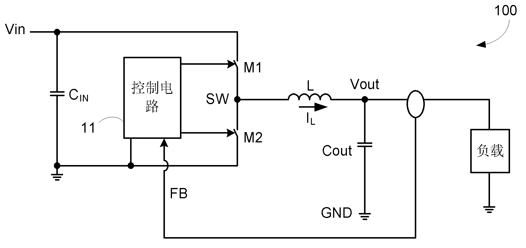
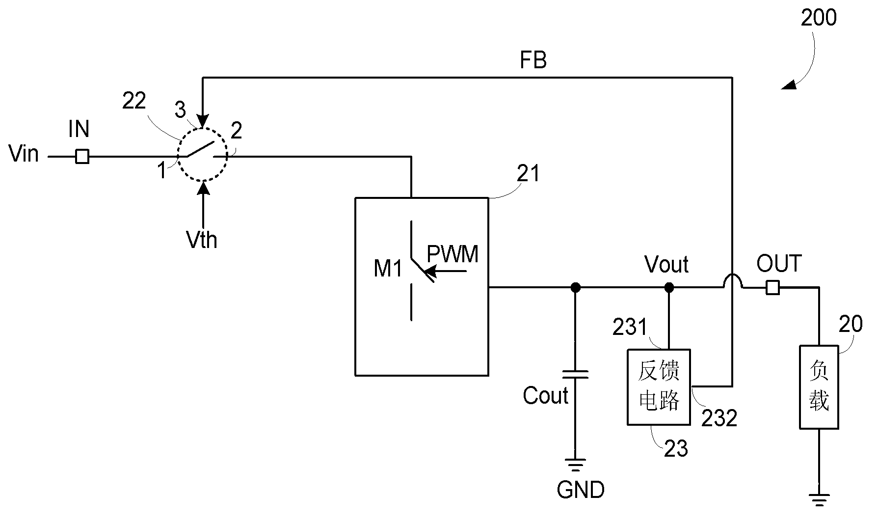
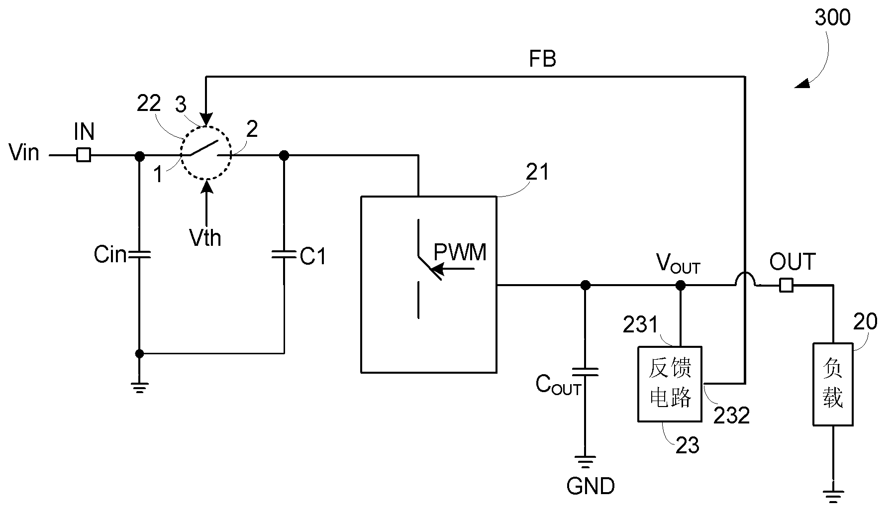
[0024] Exemplary embodiments of a voltage converter including a protection switch and a method of providing overvoltage protection in a voltage converter of the present invention are fully described below with reference to the accompanying drawings. In one embodiment, a voltage converter includes an input terminal for receiving an input voltage; an output terminal for providing an output voltage to a load; a feedback circuit including an input terminal and an output terminal, wherein the input terminal is coupled to the output terminal , the output terminal provides a feedback signal representing the output voltage; the main switch circuit, including a main switch for adjusting the output voltage, wherein the control terminal of the main switch receives a pulse width modulation signal, and the output voltage is affected by the duty ratio control of the pulse width modulation signal; and a protection switch having a first end, a second end and a control end, wherein the first en...
PUM
 Abstract
Description
Claims
Application Information
 - R&D
- Intellectual Property
- Life Sciences
- Materials
- Tech Scout
- Unparalleled Data Quality
- Higher Quality Content
- 60% Fewer Hallucinations
Browse by: Latest US Patents, China's latest patents, Technical Efficacy Thesaurus, Application Domain, Technology Topic, Popular Technical Reports.
© 2025 PatSnap. All rights reserved.Legal|Privacy policy|Modern Slavery Act Transparency Statement|Sitemap|About US| Contact US: help@patsnap.com