Magnetic material powder forming mold with non-magnetic isolating structure

A technology of isolation structure and magnetic material, applied in the field of mold manufacturing, can solve the problems of affecting performance, uneven magnetic field distribution, inconsistent blank orientation direction, etc., to achieve the effect of improving quality and performance

Active Publication Date: 2013-01-02
JIANGXI JLMAG RARE EARTH
View PDF5 Cites 5 Cited by
  • Summary
  • Abstract
  • Description
  • Claims
  • Application Information

AI Technical Summary

Problems solved by technology

[0007] In addition, due to the uneven distribution of the magnetic field, the orientation direction of the pressed blank is inconsistent in each part, which will also affect its performance.

Method used


Image

  • Magnetic material powder forming mold with non-magnetic isolating structure
  • Magnetic material powder forming mold with non-magnetic isolating structure
  • Magnetic material powder forming mold with non-magnetic isolating structure

Examples


Embodiment 1

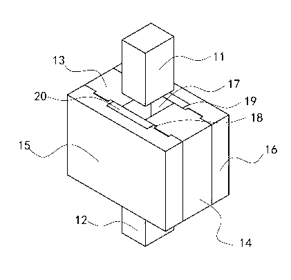
[0024] Such as figure 2 As shown, the magnetic material powder molding die with a non-magnetic isolation structure according to the present invention includes an upper pressing head 11 , a lower pressing head 12 , a female mold and an insulating structure 20 . Described female mold comprises front side plate 13, back side plate 14, left side plate 15 and right side plate 16, and described front side plate 13, described back side plate 14, described left side plate 15 and described right side plate A mold cavity 17 is formed around the side plate 16, and the upper indenter 11 and the lower indenter 12 match the mold cavity 17, and press into the mold cavity 17 from above and below the mold cavity 17 respectively. . The left side plate 15 and the right side plate 16 are respectively provided with concave structures 18, 19 on one side in the mold cavity 17, the isolation structure 20 cooperates with the concave structures 18, 19, and the isolation structure 19 is made of non-m...

Embodiment 2

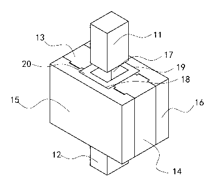
[0029] Such as image 3 As shown, the isolation structure 20 is a hollow cylindrical body, and its cross section can be square or rectangular. Two opposite sides of the cylindrical body are respectively located in the concave structures 18, 19, and the other two opposite sides are respectively connected The inner sides of the front side plate 13 and the rear side plate 14 are in close contact. By adopting this embodiment, the isolation structure 20 is taken as a whole, which is convenient for installation. When adopting this embodiment, the length of the front side plate 13 and the rear side plate 14 needs to be shortened adaptively, that is, the area of ​​the mold cavity 17 is enlarged, and then the isolation structure 20 is placed on the mold cavity 17 The inner wall is easy to install.


PUM

PropertyMeasurementUnit
thicknessaaaaaaaaaa
thicknessaaaaaaaaaa

Abstract

The invention discloses a magnetic material powder forming mold with a non-magnetic isolating structure. The magnetic material powder forming mold comprises a female die and an isolating structure, wherein the female die comprises a front side plate, a rear side plate, a left side plate and a right side plate; the front side plate, the rear side plate, the left side plate and the right side plate are enclosed to form a mold cavity; concave structures which are matched with the isolating structure are arranged on the left side plate and the right side plate on one side in the mold cavity; and the isolating structure is positioned in the concave structures and is made of a non-magnetic material. According to the magnetic material powder forming mold, the non-magnetic isolating structures are arranged inside the left side plate and the right side plate, suction force of the left side plate and the right side plate stressed during movement of the magnetic powder in the mold cavity is overcome, and the magnetic powder is prevented from being sucked to the left side and the right side of the mold cavity by the left side plate and the right side plate, so that a finally formed blank is prevented from being formed into a waist shrinkage shape with two large ends and a small middle part, and the quality and the performance of the blank made through the mold are improved.

Description

technical field [0001] The invention relates to the field of mold manufacturing, in particular to a magnetic material powder forming mold with a non-magnetic isolation structure. Background technique [0002] Such as figure 1 As shown, the mold currently used is composed of a female mold, an upper indenter 5, and a lower indenter 6. The female mold is composed of four side plates, front, rear, left, and right. Among them, the left side plate 1 and the right side plate 2 use magnetic materials, generally Gr12 steel or GGr15 steel; the front side plate 3 and the rear side plate 4 are non-magnetic materials, generally 304 stainless steel, non-magnetic die steel, non-magnetic hard alloy, etc. The upper pressure head 5 and the lower pressure head 6 are also non-magnetic materials. Magnetic material. [0003] The magnetic powder needs to have a magnetic field orientation during the pressing process, so that the magnetization direction of the powder is the same as the direction o...

Claims


Application Information

Patent Timeline
Patent Type & Authority Applications(China)
IPC IPC(8): B22F3/03
Inventor 蔡报贵周铁夫金小平胡勇毛华云岳崇斌
Owner JIANGXI JLMAG RARE EARTH
Why Eureka
Try Eureka